Headlamp control circuit

a control circuit and headlamp technology, applied in electric vehicles, signalling/lighting devices, transportation and packaging, etc., can solve the problem that all headlamps are brought into a lights-out condition

Inactive Publication Date: 2010-02-09
SUMITOMO WIRING SYST LTD
View PDF15 Cites 6 Cited by
  • Summary
  • Abstract
  • Description
  • Claims
  • Application Information

AI Technical Summary

Benefits of technology

[0014]With the above construction, the low-beam lighting signal output section outputs a signal for turning the first and second switch sections on if the indication reception section accepts either the low-beam lighting indication or the high-beam lighting indication. Also, the high-beam lighting signal output section outputs a signal for turning the third switch section on, when the indication reception section accepts the high-beam lighting indication. The forced-off section compulsorily turns the first and second switch sections off when the third switch section turns on and the output voltage detecting section detects the high-beam lighting voltage, regardless of any signal supplied from the low-beam lighting signal output section. Accordingly, when the indication reception section accepts the high-beam lighting indication, only the third and fourth luminescent parts for high-beam are driven to light the high-beam lighting in the two-lamp system headlight. In this case, the output voltage detecting section does not detect the high-beam lighting voltage when the third switch section fails under a high-beam condition. Thus, the first and second switch sections are not compulsorily turned off. Consequently, the first and second switch sections are turned on in accordance with the signal supplied from the low-beam lighting signal output section and the first and second luminescent parts for low-beam are lit. Accordingly, the headlamp control circuit for controlling a two-lamp headlight system reduces a possibility that all headlamps are brought into lights-out even if the third switch section fails under the high-beam condition while the single third switch section drives the third and fourth luminescent parts for high-beam lighting.
[0016]The third switch section may be a semiconductor switch. The semiconductor switch is less reliable and more likely to fail than a mechanical relay. However, the semiconductor switch facilitates downsizing of the third switch section, and it is possible to reduce a possibility that all headlamps are brought into lights-out by using the above-described headlamp control section in the lighting control of the two-lamp system headlight, even if the third switch section fails under a high-beam condition.
[0018]In the above-described headlamp control, circuit, the third switch section is turned on when the indication reception section accepts the high-beam lighting indication and the third and fourth luminescent parts for high-beam connected to the third and fourth connecting terminals are lit. Also, the first and second switch sections are turned on and the first and second luminescent parts for low-beam connected to the first and second connecting terminals are lit when the indication reception section accepts the low-beam indication. The case where the indication reception section accepts the high-beam lighting indication and the output voltage detecting section does not detect the high-beam lighting voltage will be taken for the case where the third and fourth luminescent parts for high-beam are not lit due to a failure in the third switch section. Thus, the control circuit lights the first and second luminescent parts for low-beam. It is possible to reduce a possibility that all headlamps are brought into lights-out when such headlamp control circuit is used in a lighting control for a two-lamp system headlight, even if the third switch section fails under the high-beam condition while the single third switch section drives to light the third and fourth luminescent parts for high-beam.

Problems solved by technology

However, if a single switching element drives the lighting of right and left high-beam headlamps in the two-lamp system, there has been a trouble that all headlamps are brought into a lights-out condition if the switching element fails under a high-beam condition.

Method used


Image

  • Headlamp control circuit
  • Headlamp control circuit
  • Headlamp control circuit

Examples


Embodiment Construction

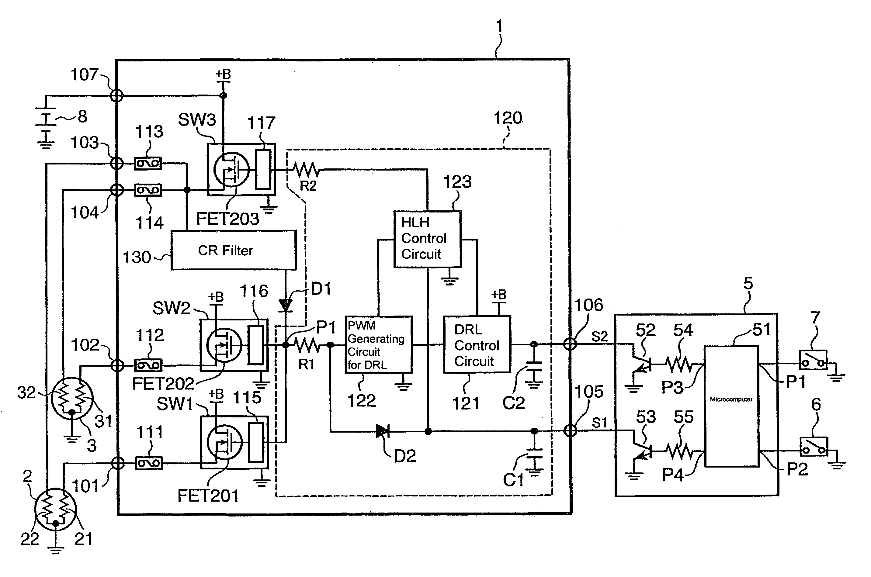
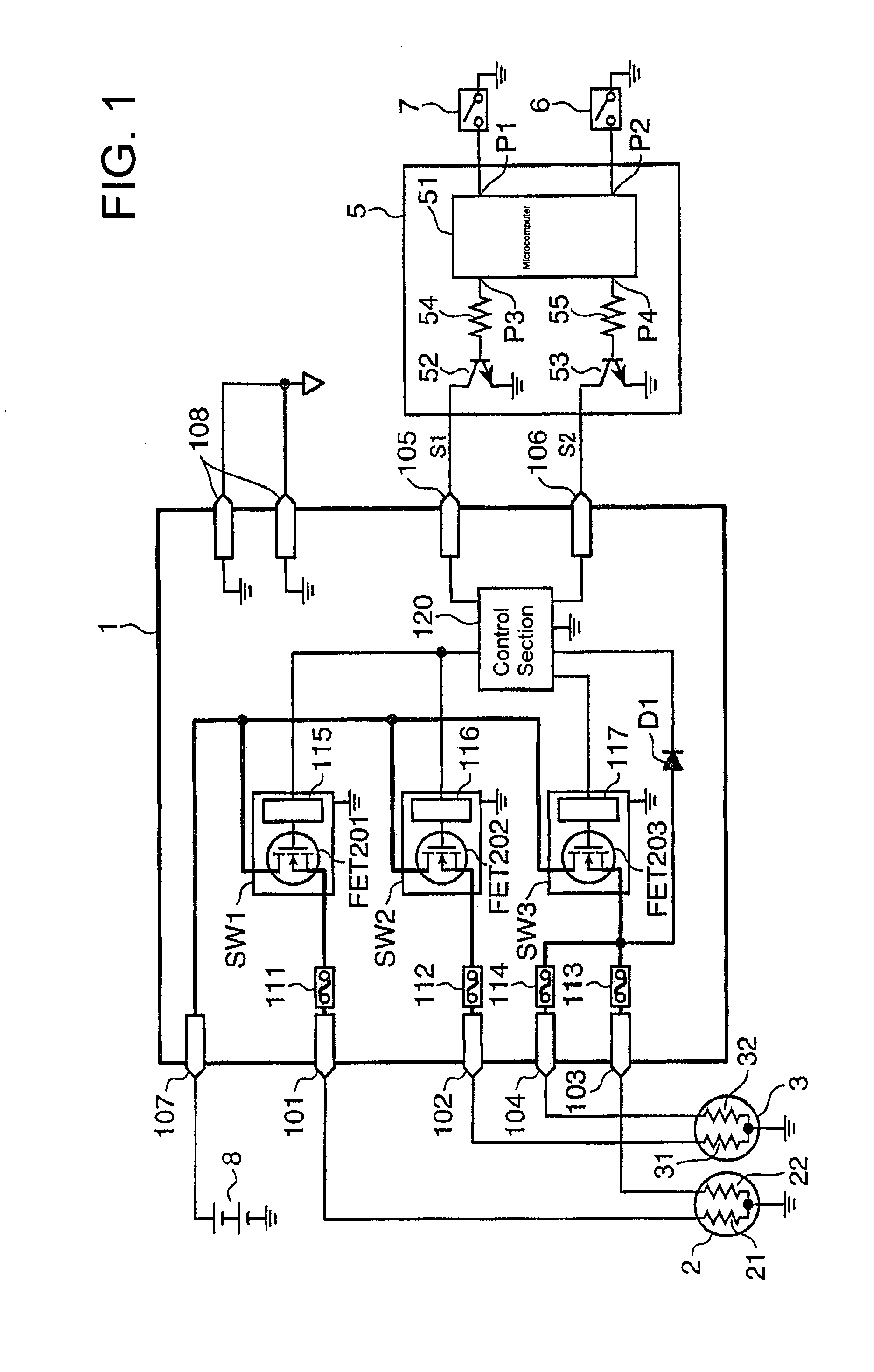
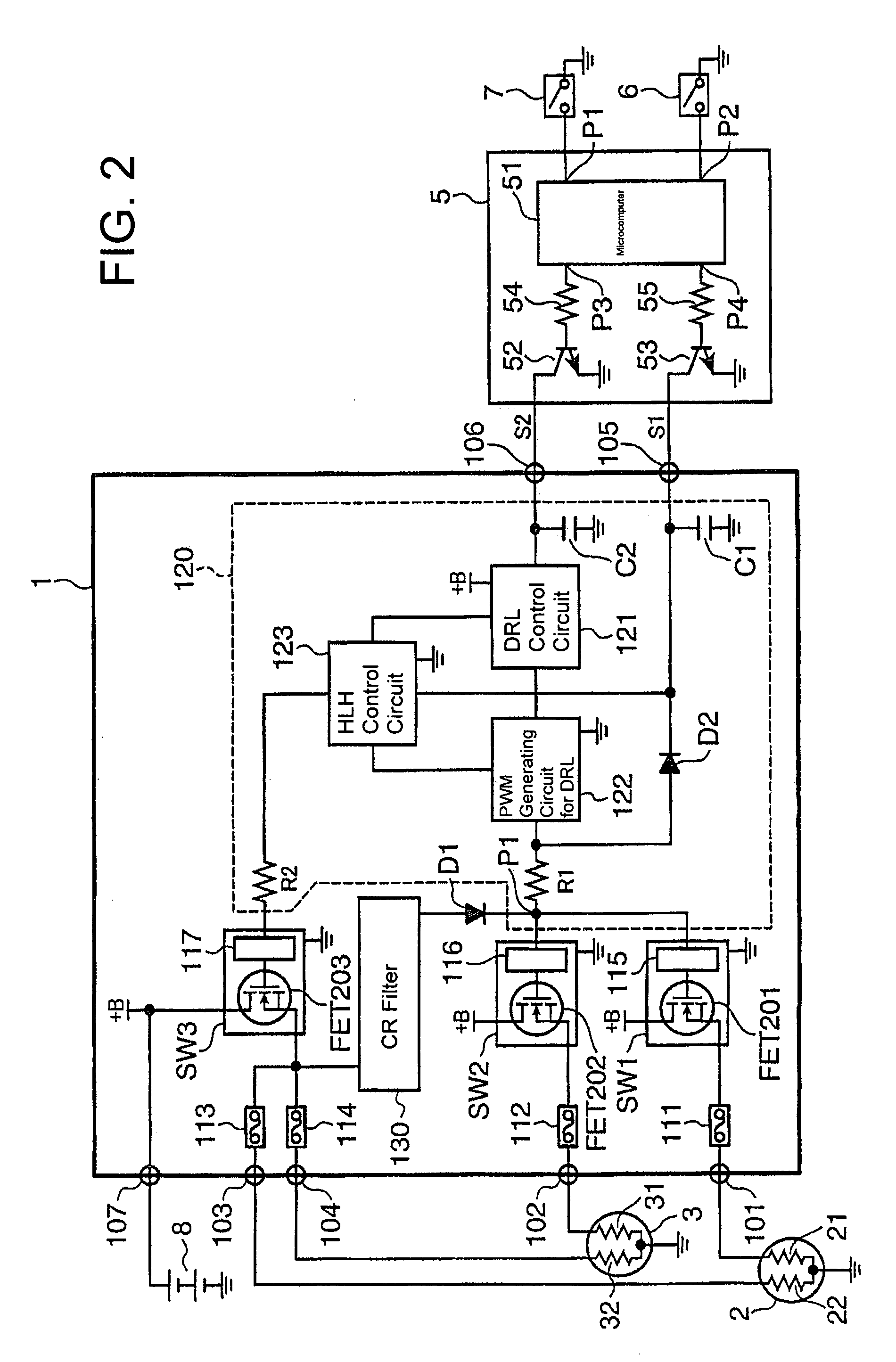
[0026]The headlamp control system shown in FIG. 1 includes a headlamp control circuit 1, a left headlamp 2, a right headlamp 3, an ECU (Electric Control Unit) 5, operation switches 6 and 7, and a battery 8.

[0027]The left headlamp 2 includes a low-beam filament (first luminescent part) 21 and a high-beam filament (third luminescent part) 22. The right headlamp 3 includes a low-beam filament (second luminescent part) 31 and a high-beam filament (fourth luminescent part) 32. The ECU 5 includes a microcomputer 51, transistors 52 and 53, and resisters 54 and 55.

[0028]Signal input terminals P1 and P2 of the microcomputer 51 are connected to the operation switches 6 and 7, respectively. A signal output terminal P3 of the microcomputer 51 is connected through the resister 54 to a base of the transistor 52 and an emitter of the transistor 52 is connected to the ground. A signal output terminal P4 of the microcomputer 51 is connected through the resister 55 to a base of the transistor 53 and ...


PUM


Abstract

A headlamp control circuit reduces a possibility that all headlamps become lights-out in a two-lamp system headlight, even if a switching element fails under a high-beam condition while the single switching element is driven to light two right and left high-beam filaments. A headlamp control circuit includes switch sections (SW1) and (SW2) for lighting low-beam filaments (21) and (31), a switch section (SW3) for lighting high-beam filaments (22) and (32) together, a diode (D1) for detecting an output voltage on the switch section SW3, and a control section (120) for turning the switch section (SW3) to an on-condition in the case where a high-beam indication is accepted and for turning the switch sections (SW1) and (SW2) to an on-condition in the case where a low-beam indication is accepted and in the case where a high-beam indication is accepted and the diode (D1) detects no high-beam lighting voltage.

Description

BACKGROUND OF THE INVENTION[0001]1. Field of the Invention[0002]This invention relates to a headlamp control circuit that controls a drive of lighting headlamps on a vehicle.[0003]2. Description of the Related Art[0004]Known headlamp systems for a vehicle typically have four-lamps or two-lamps. The four-lamp system has a high-beam headlamp and a low-beam headlamp on each of the right and left sides of a vehicle. The two-lamp system has a high-beam filament and a low-beam filament on each of the right and left sides of the vehicle.[0005]Only the right and left low-beam headlamps of the four-lamp system are lit to make a low-beam condition. However, all four lamps of the four-lamp system are lit to make a high-beam condition.[0006]The right and left low-beam filaments of the two-lamp system are lit to make a low-beam condition, and all four filaments of the two-lamp system also are lit to make a high-beam condition.[0007]A headlamp control circuit that controls a drive of lighting the...

Claims


Application Information

Patent Timeline
Patent Type & Authority Patents(United States)
IPC IPC(8): B60Q1/02
CPCB60Q1/1415B60Q11/005
Inventor ASADA, KAZUHIRO
Owner SUMITOMO WIRING SYST LTD
Why Eureka
Try Eureka