
Electronic draft control for trailed implements

a technology of electronic draft control and trailed implements, which is applied in the field of ground-engaging implements, can solve the problems of engine blockage, engine blockage, and vehicle motion halt, and achieve the effects of reducing operator fatigue, increasing productivity, and durable construction

Inactive Publication Date: 2008-10-23
CNH IND AMERICA LLC
View PDF14 Cites 50 Cited by
  • Summary
  • Abstract
  • Description
  • Claims
  • Application Information

AI Technical Summary

Benefits of technology

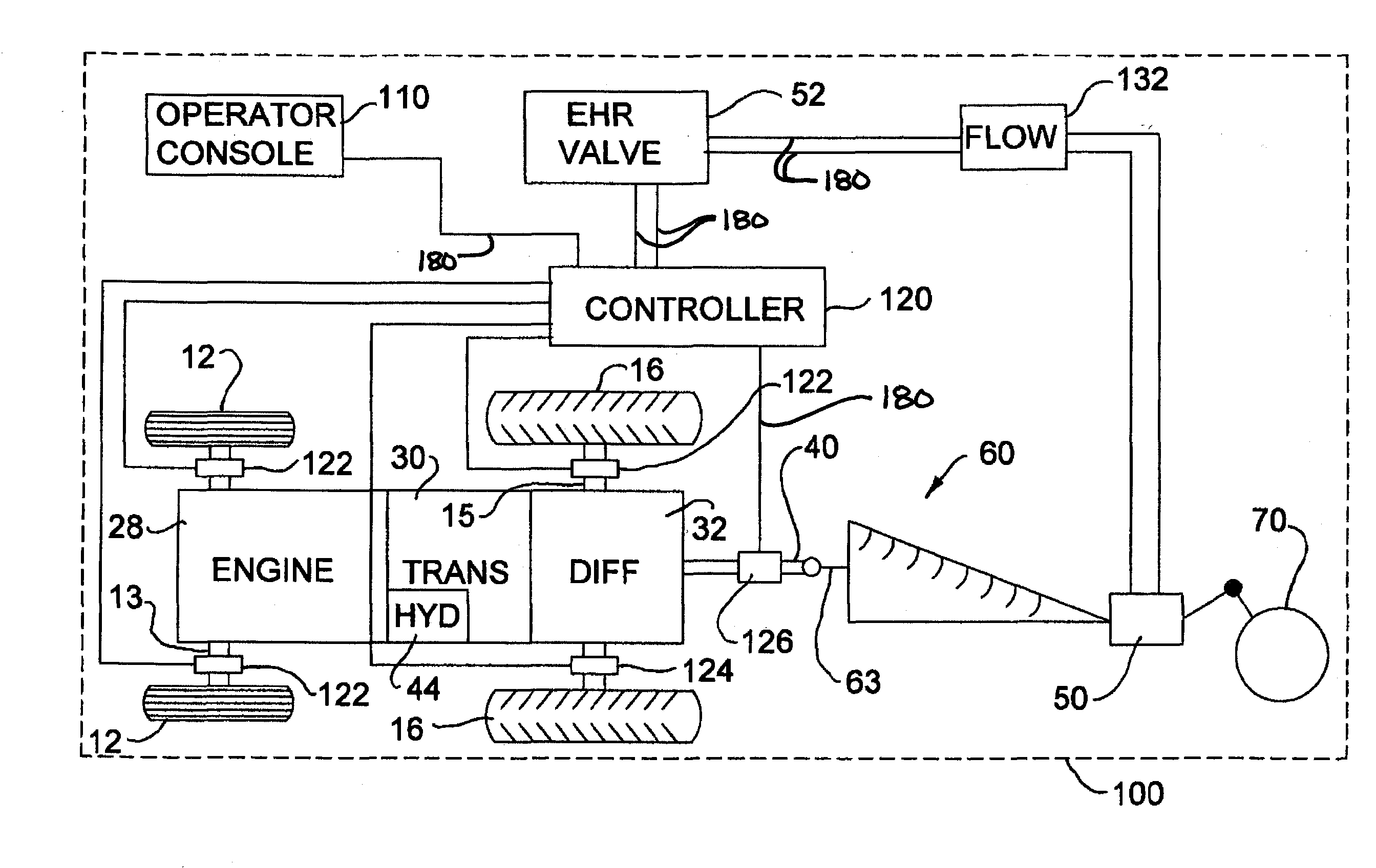
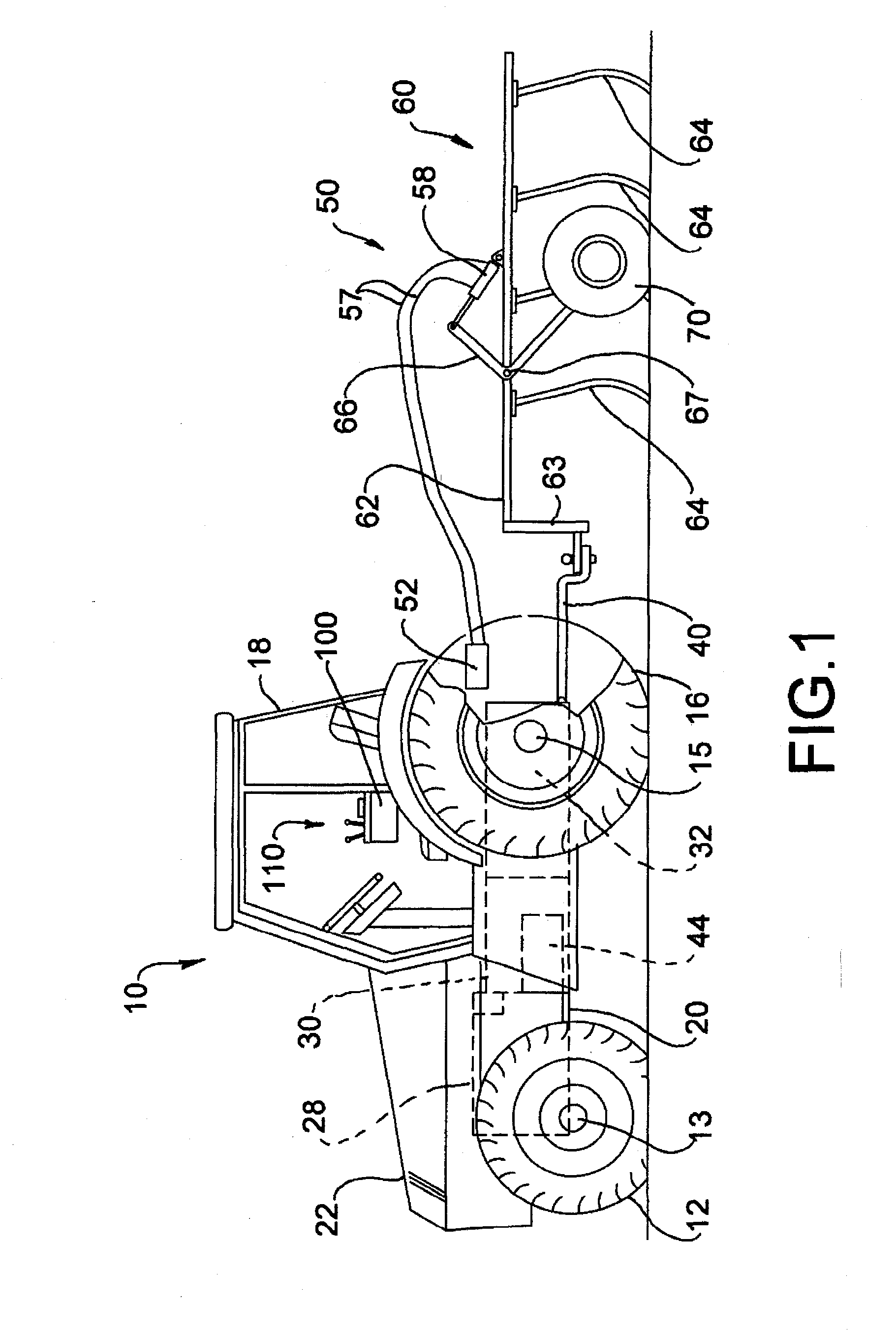
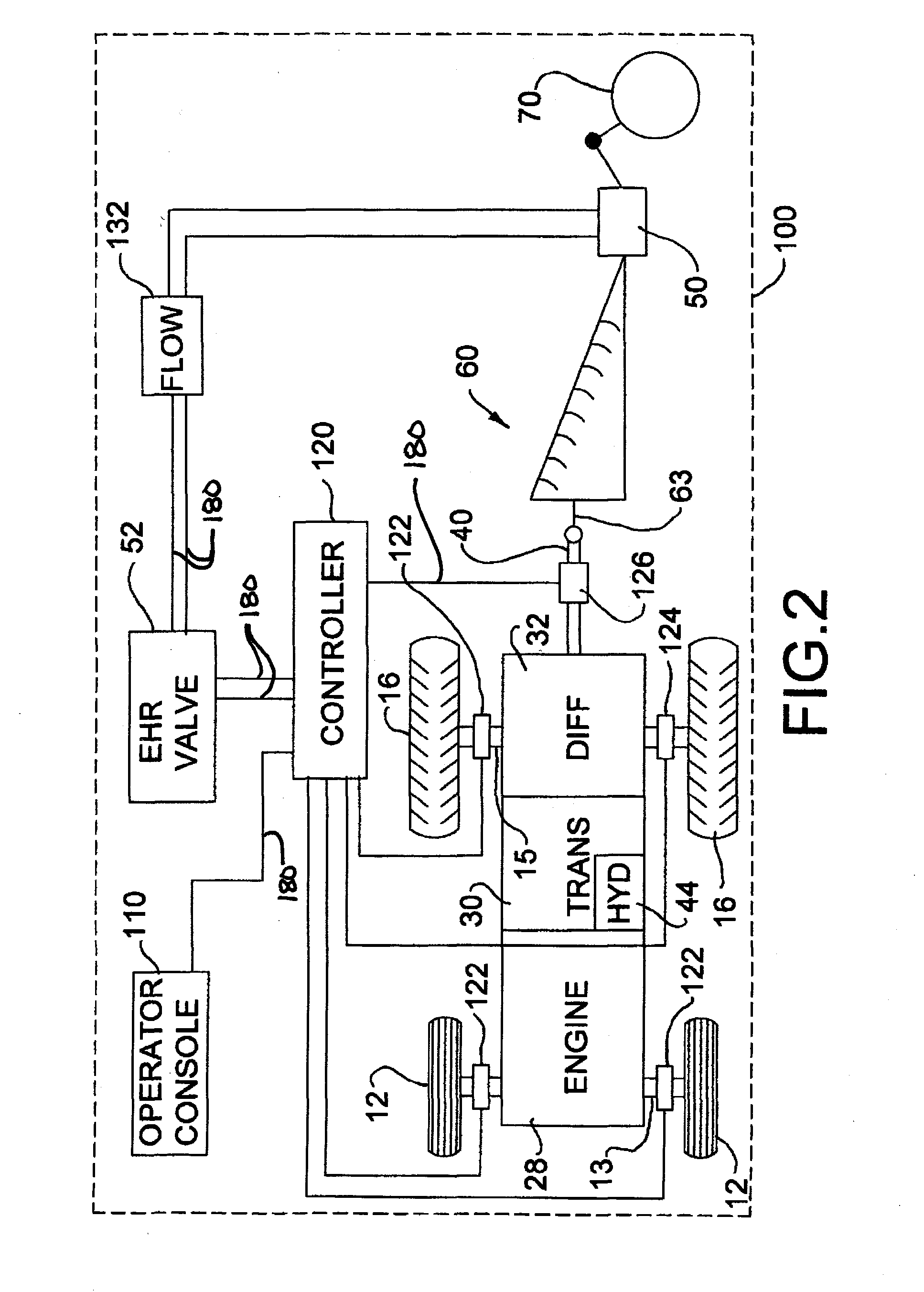
[0010]It is a further object of the present invention to provide an electronic draft control system for an agricultural tractor towing trailed, ground-engaging implements that adjusts the implement position in relation to the ground to maintain a more accurate, consistent draft load on the tractor.
[0018]These and other objects are achieved by providing a draft load control system for an agricultural tractor towing a trailed, ground-engaging implement that monitors implement height using sensors located on the tractor or communicating with the control system using an on-board tractor control communication system and adjusts the implement position in relation to the ground based on draft load, implement height, and tractor wheel-slip to maintain a more accurate, consistent draft load on the tractor while maintaining the implement engaged with the ground and preventing the tractor-implement ground speed from being reduced to zero.

Problems solved by technology

When the operator finishes manipulating the device, the implement remains in the position set by the operator, but will not, however, maintain a desired depth of engagement or implement draft load as the tractor and implement move across the ground.
Similarly, changes in draft load may cause the engine to be bogged down, requiring operator adjustment of implement position to avoid stalling the engine.
In other situations, increasing draft load may cause increased wheel slippage leading ultimately to a halting of vehicle motion.
Efforts to automatically control the draft load by repositioning a trailed implement to vary its depth of ground engagement have been problematic.
Adding such sensors to implements subjects those sensors to harsh operating conditions which lead to increased failure rates.
Depth control alone is not sufficient to control draft load with the required precision.
Even depth control combined with draft load measurement is still insufficient under some conditions.
If wheel slippage occurs, the response of conventional EDC systems is generally counterproductive as excessive slippage generally causes a decrease in the draft load.
Such action when wheel slip is present can, if undetected or unmonitored, lead to stalling the tractor-implement combination.

Method used


Image

  • Electronic draft control for trailed implements
  • Electronic draft control for trailed implements
  • Electronic draft control for trailed implements

Examples


Embodiment Construction

)

[0024]Many of the fastening, connection, processes and other means and components utilized in this invention are widely known and used in the field of the invention described, and their exact nature or type is not necessary for an understanding and use of the invention by a person skilled in the art, and they will not therefore be discussed in significant detail. Also, any reference herein to the terms “left” or “right,”“up” or “down,” or “top” or “bottom” are used as a matter of mere convenience, and are determined by standing at the rear of the machine facing in its normal direction of travel. Furthermore, the various components shown or described herein for any specific application of this invention can be varied or altered as anticipated by this invention and the practice of a specific application of any element may already be widely known or used in the art by persons skilled in the art and each will likewise not therefore be discussed in significant detail. When referring to ...


PUM


Abstract

A draft load control system for an agricultural tractor towing a trailed, ground-engaging implement that monitors implement height using sensors located on the tractor or sensors coupled to an on-board control communications system and adjusts the implement position in relation to the ground based on draft load, implement height, and tractor wheel-slip to maintain a more accurate, consistent draft load on the tractor while maintaining the implement engaged with the ground and preventing the tractor-implement ground speed from being reduced to zero.

Description

BACKGROUND OF THE INVENTION[0001]The present invention relates generally to ground-engaging implements towed by agricultural tractors and more particularly to systems and methods for monitoring implement position and controlling the draft load caused by an implement as it is moved across the ground by a tractor.[0002]One of the most common uses of agricultural tractors is to move implements through agricultural fields to cultivate and condition the soil. Implements are commonly connected for towing by the tractor using a three-point hitch or towed using a drawbar. A three-point hitch typically comprises two bottom lift arms, to which the implement is connected in rotary manner to selectively pivot about a given hinge axis; and a top link interposed between the tractor frame and the implement to control the angular position of the implement about the hinge axis. The lift arms are moved by a further actuating cylinder (or cylinders) interposed between the tractor frame and the lift ar...

Claims


Application Information

Patent Timeline
Patent Type & Authority Applications(United States)
IPC IPC(8): A01B63/14A01B63/22G06G7/00
CPCA01B63/145A01B63/22
Inventor FOSTER, CHRISKEPLINGER, JOHNNYSMITH, KEVIN M.POSSELIUS, JOHN
Owner CNH IND AMERICA LLC
Learn More