

Storage box for electronic apparatus
a technology for electronic equipment and storage boxes, which is applied in the direction of electric equipment casings/cabinets/drawers, instruments, machines/engines, etc., can solve the problems of operating sound or noise of apparatuses, and achieve the effect of further reducing sound transmission
- Summary
- Abstract
- Description
- Claims
- Application Information
AI Technical Summary
Benefits of technology
Problems solved by technology
Method used
Image


Examples
first embodiment
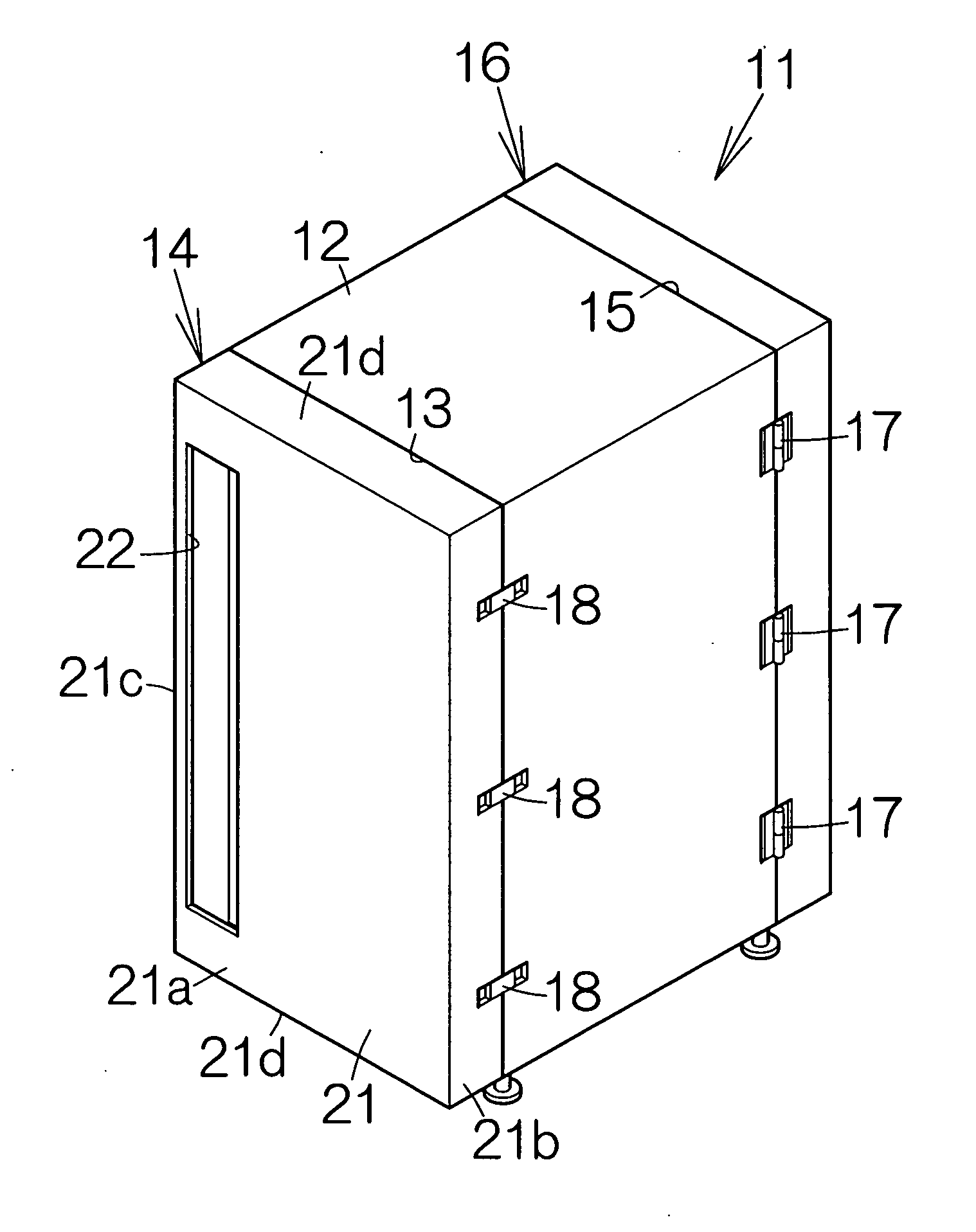
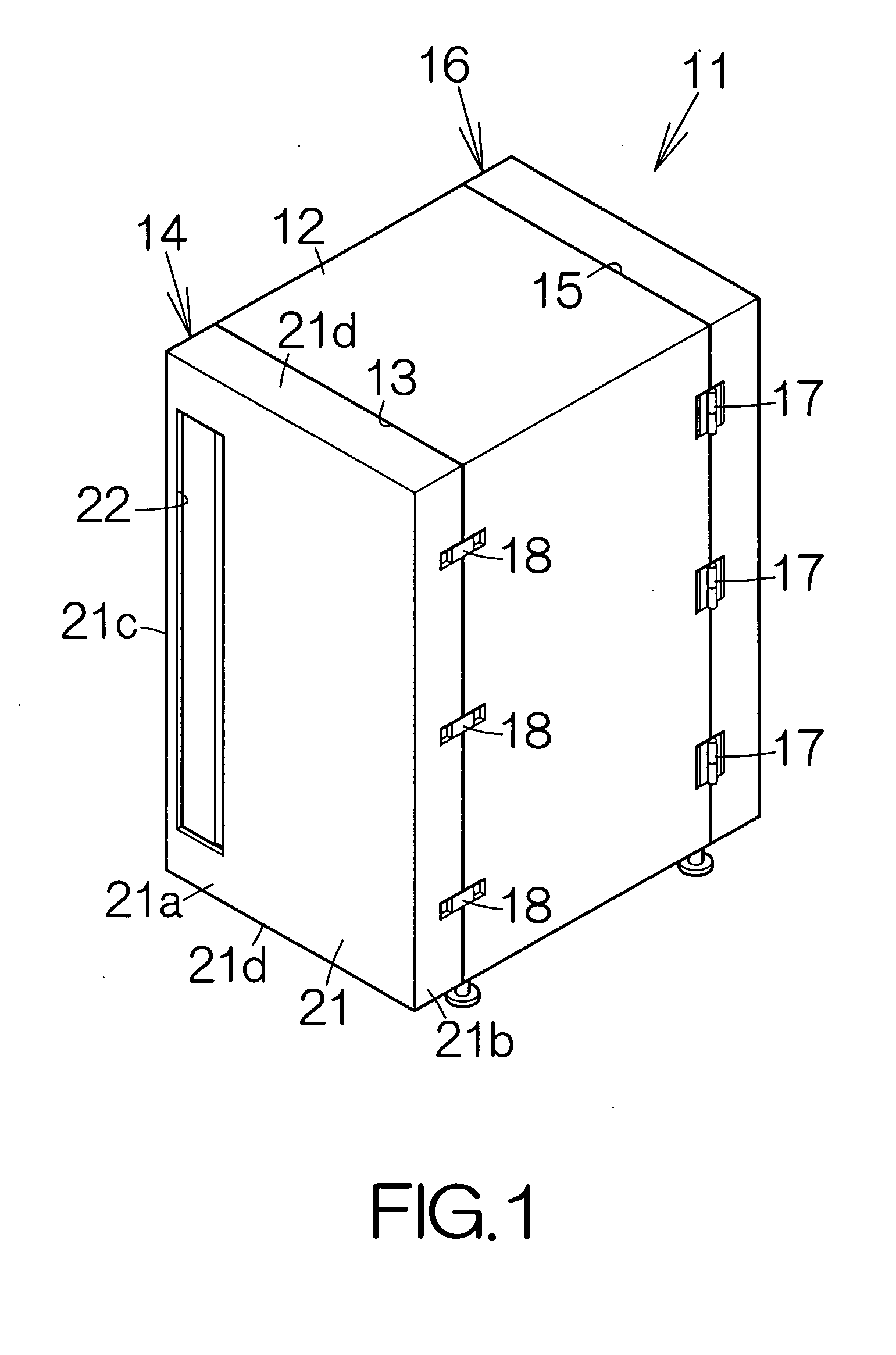
[0125]FIG. 1 schematically illustrates a storage box 11, for an electronic apparatus, according to the present invention. The storage box 11 includes a box-shaped enclosure 12. A first door 14 is designed to close a first plane, namely a front surface 13 of the box-shaped enclosure 12. A second door 16 is designed to close a second plane, namely a back surface 15 of the box-shaped enclosure 12. The first door 14 and the second door 16 are coupled to the box-shaped enclosure 12 for relative swinging movement, namely for opening and closing operations. Hinges 17 may be utilized to couple the first and second doors 14, 16, for example. The first door 14 and the second door 16 are respectively allowed to swing around hinge pins of the hinges 17. The hinges 17 accept the attachment and detachment of the first door 14 and the second door 16 to and from the box-shaped enclosure 12. Latches 18 in combination with the hinges 17 serve to make the first door 14 and the second door 16 tightly c...
second embodiment
[0165]FIG. 13 schematically illustrates a storage box 11a, for an electronic apparatus, according to the present invention. The storage box 11a includes the first door 14 defining the first ventilation opening 22 comprising a window opening elongated in the horizontal direction. The first ventilation opening 22 extends along the edge defined between the first outer wall member 21a and the fourth outer wall member 21d of the upper end. As shown in FIG. 14, the first through opening 28 comprises a window opening elongated in the horizontal direction. The first through opening 28 extends along the edge defined between the first deadening wall member 26 and the fourth outer wall member 21d of the lower end. The first ventilators 31 are arranged in the horizontal direction.
[0166]As shown in FIG. 15, the second ventilation opening 24 extends along the edge defined between the first outer wall member 23a and the fourth outer wall member 23d of the lower end. The second through opening 41 i...
third embodiment
[0167]FIG. 16 schematically illustrates a storage box 11b, for an electronic apparatus, according to the present invention. The storage box 11b includes the first door 14 defining the first ventilation opening 22 in the upper one of the fourth outer wall members 21d of the first auxiliary box-shaped enclosure 21. The first ventilation opening 22 is thus formed at the top of the first auxiliary space 47. The first ventilation opening 22 extends along the edge defined between the first outer wall member 21a and the fourth outer wall member 21d of the upper end. The first ventilation opening 22 is a window opening elongated in the horizontal direction in the same manner as described above.
[0168]The second ventilation opening 24 is defined at the top of the second auxiliary space 48. The second ventilation opening 24 extends along the edge defined between the first outer wall member 23a and the fourth outer wall member 23d of the upper end. The second through opening 41 extends along th...
PUM
| Property | Measurement | Unit |
|---|---|---|
| distance | aaaaa | aaaaa |
| speed | aaaaa | aaaaa |
| diameter | aaaaa | aaaaa |
Abstract
Description
Claims
Application Information