Thermally enhanced battery module
- Summary
- Abstract
- Description
- Claims
- Application Information
AI Technical Summary
Benefits of technology
Problems solved by technology
Method used
Image

Examples
first embodiment
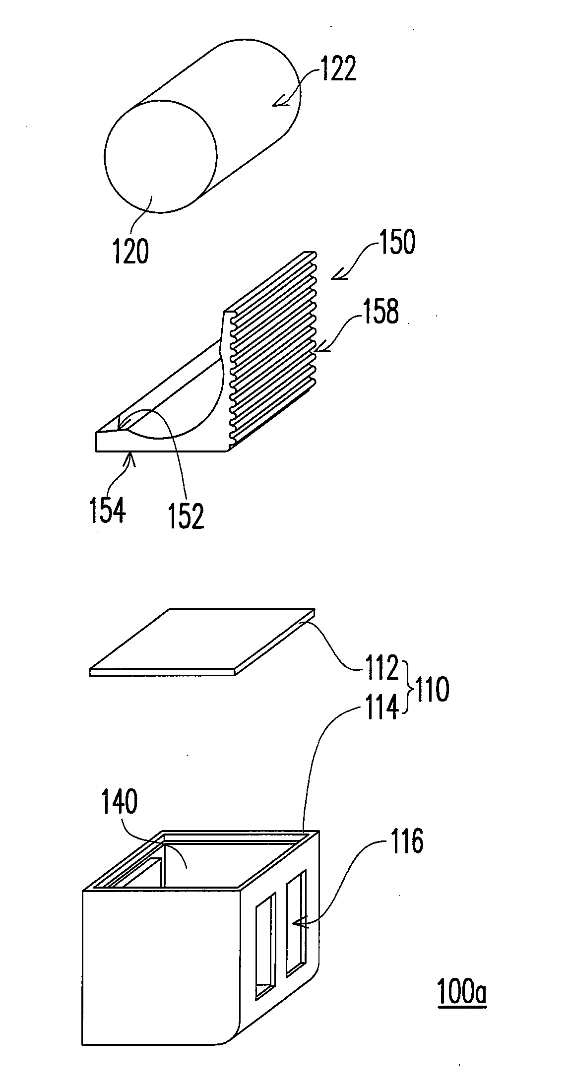
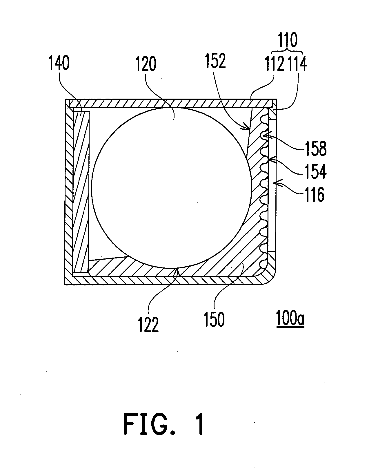
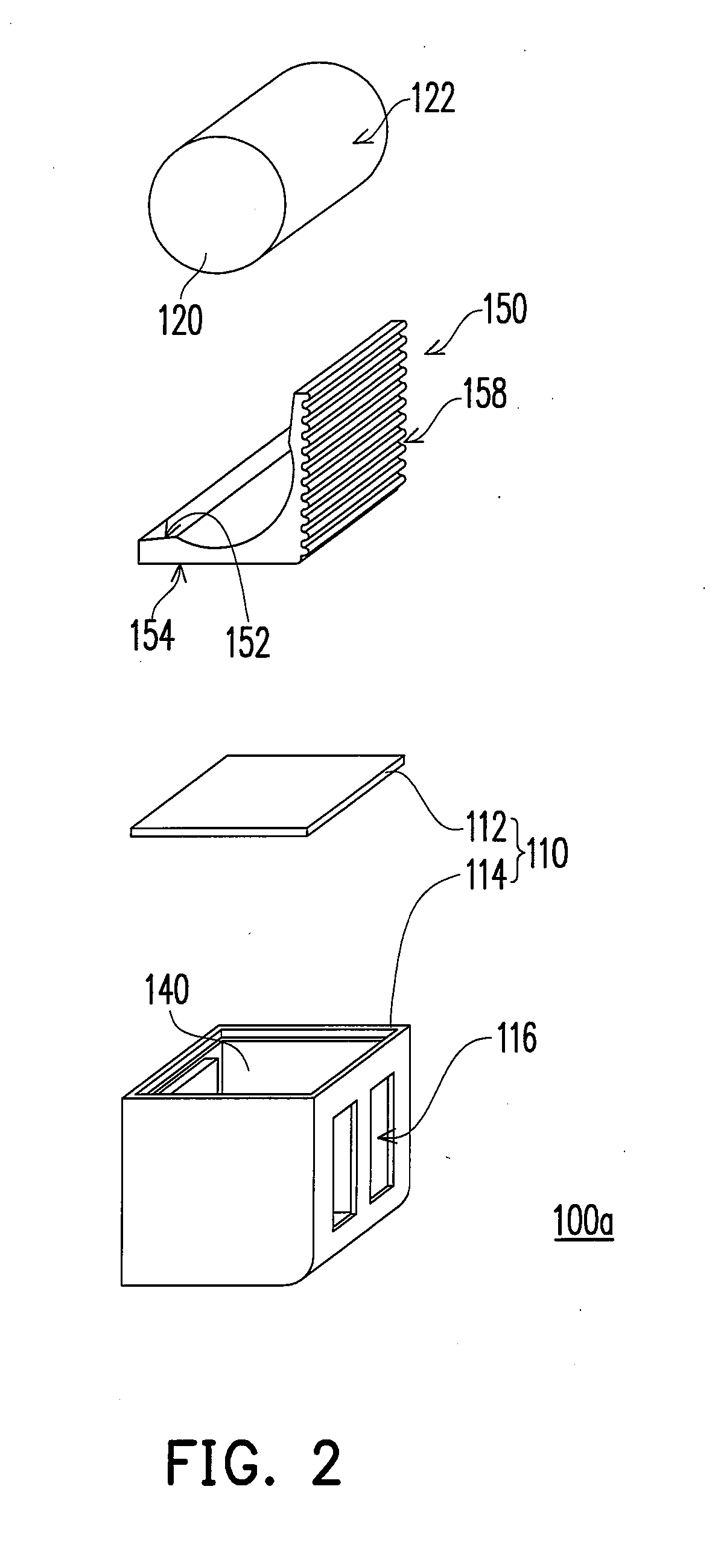
[0028]FIG. 1 is a schematic diagram showing the structure of a thermally enhanced battery module according to the first embodiment of the invention. FIG. 2 is an exploded diagram showing the thermally enhanced battery module in FIG. 1. The thermally enhanced battery module 110a includes a casing 110, a cell 120 and a heat dissipation fin 150. The casing 110 includes a cover 112 and a main body 114 and has one or more than one openings 116 located at one side of the main body 114. The material of the cover 112 and the main body 114 is insulator such as plastic. The cover 112 and the main body 114 cover the cell 120 and the heat dissipation fin 150, and the openings 116 at the main body 114 expose part of the heat dissipation fin 150.
[0029]In detail, the shape of the cell 120 is, for example, column-shaped and has a contact surface 122. The shape of the heat dissipation fin 150 is, for example, about L post-shaped and has an inner surface 152, an outer surface 154 and a plurality of n...
second embodiment
[0033]FIG. 3 is a schematic diagram showing a thermally enhanced battery module according to the second embodiment of the invention. FIG. 4 is an exploded diagram showing the thermally enhanced battery module in FIG. 3. The thermally enhanced battery module 110b includes a casing 110, a first row of cells 120a, a second row of cells 120b, a control circuit board 140 and a heat dissipation fin 150. The first row of cells 120a and the second row of cells 120b are, for example, formed by connecting a plurality of cells 120 in the first embodiment in series. Part of the inner surface 152 of the heat dissipation fin 150 contacts the surfaces of the first row of cells 120a and the second row of cells 120b. In addition, the structure, material and composing manner of the casing 110, the cells 120, the control circuit board 140 and the heat dissipation fin 150 are the same with that of the first embodiment, and therefore, they are not described for concise purpose.
[0034]In detail, part of t...
third embodiment
[0036]FIG. 5 is a schematic diagram showing the structure of a thermally enhanced battery module according to the third embodiment of the invention. FIG. 6 is an exploded diagram showing the thermally enhanced battery module in FIG. 5. The structure of the thermally enhanced battery module 110c of the third embodiment is about same with that of the thermally enhanced battery module 100b of the second embodiment. The difference between them is that the number of heat dissipation fin 150 and the section shape thereof, the number of the notches 158 of the heat dissipation fin 150 and the shape of the openings 116 at the main body 114 in the thermally enhanced battery module 110c are different from those of the thermally enhanced battery module 100b in the second embodiment.
[0037]In the third embodiment, the thermally enhanced battery module 100b includes three heat dissipation fins 150 corresponding to the cells 120 of the first row of cells 120a and the second row of cells 120b. The n...
PUM
 Abstract
Description
Claims
Application Information