Creating Non-transit Nodes in a Link State Network

a link state network and non-transit node technology, applied in the field of sharing routing information, can solve the problems of not working the technique used in distance vector protocols when using link state protocols, and the modification of the link state protocol used on all other routers in the sub-network is not desirabl

Inactive Publication Date: 2008-10-23
CISCO TECH INC
View PDF13 Cites 91 Cited by
  • Summary
  • Abstract
  • Description
  • Claims
  • Application Information

AI Technical Summary

Problems solved by technology

However, techniques used in distance vector protocols do not work when using a link state protocol, because each node in a link state protocol builds its own model of the entire sub-network that uses the link state protocol.
Furthermore, modifications to the link state protocol used on all other routers in the sub-network is not desirable because there are a large number of such routers already deployed.

Method used


Image

  • Creating Non-transit Nodes in a Link State Network
  • Creating Non-transit Nodes in a Link State Network
  • Creating Non-transit Nodes in a Link State Network

Examples


Embodiment Construction

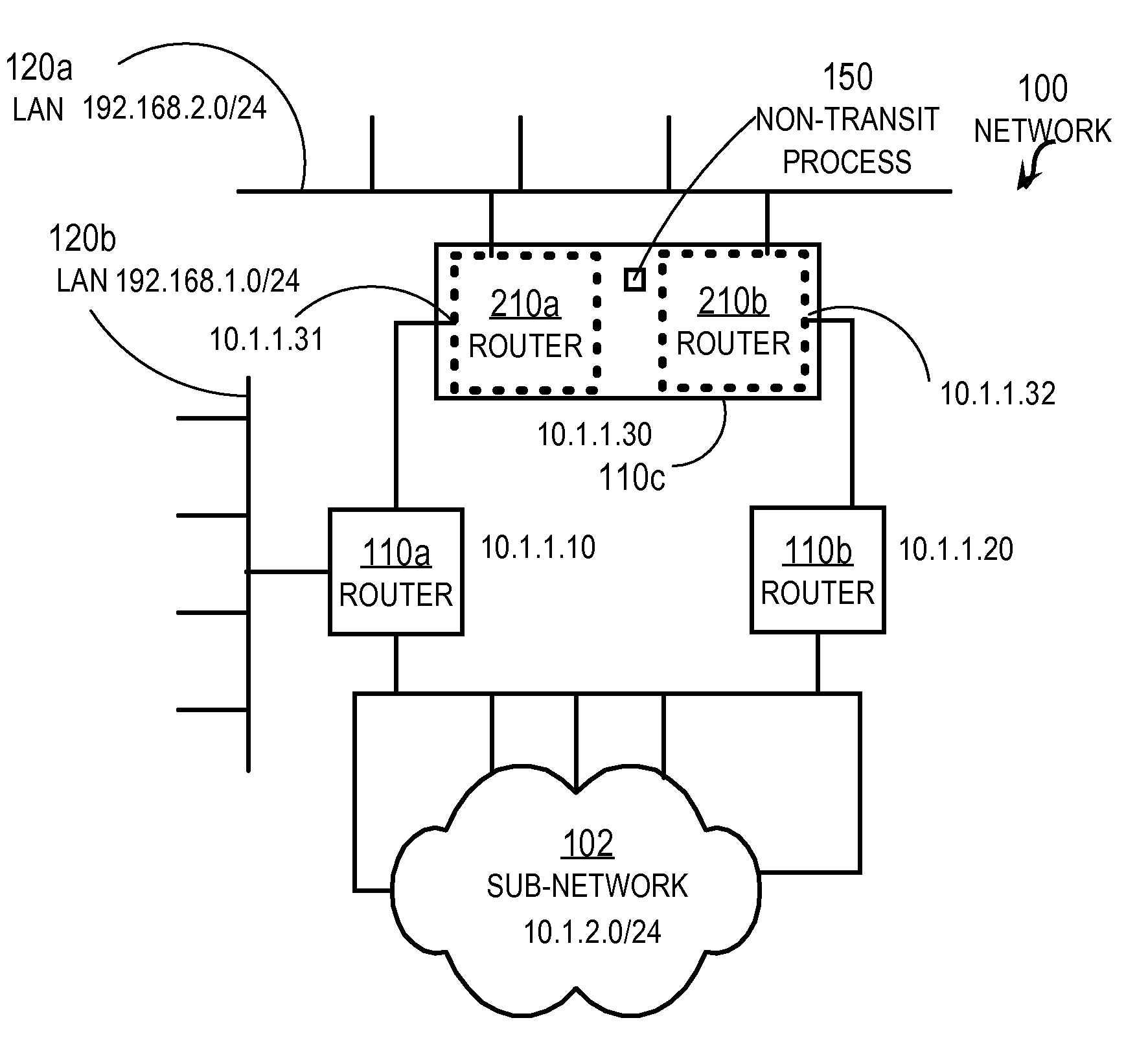
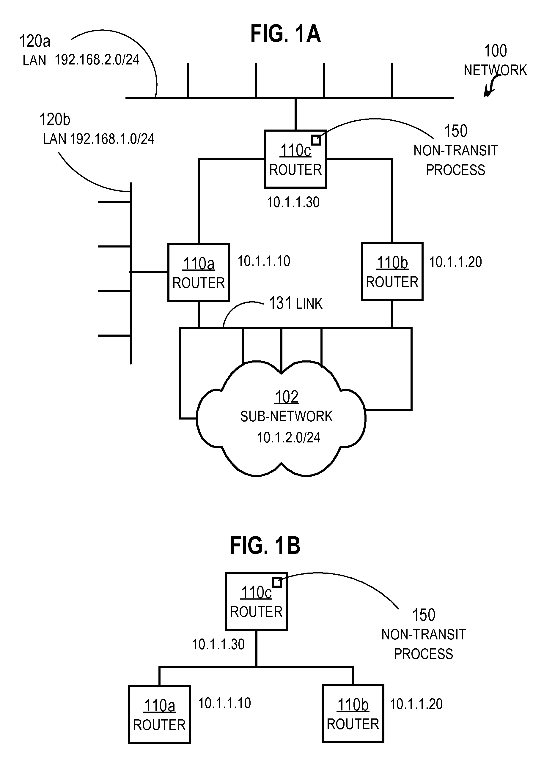
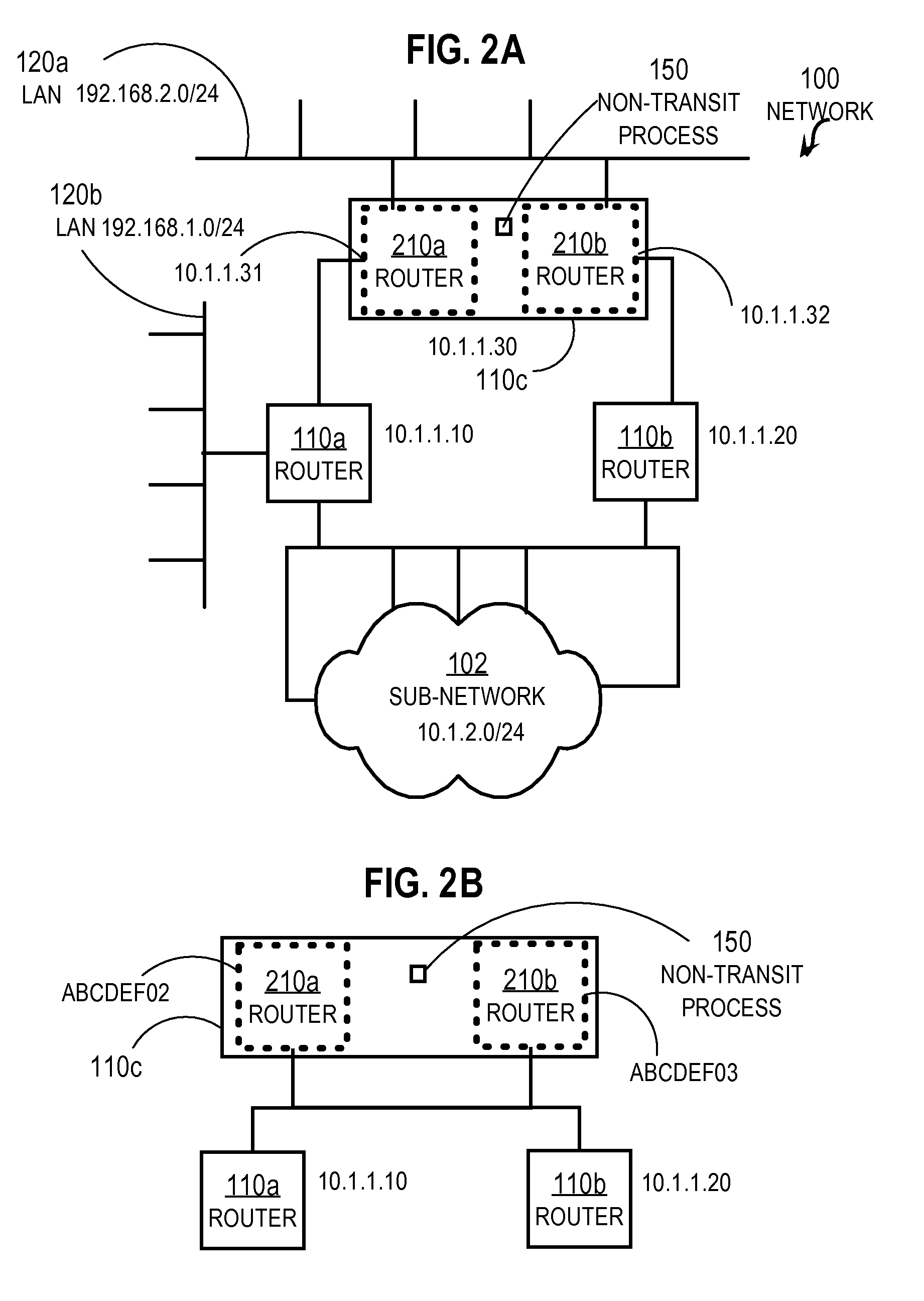
[0015]Techniques are described for creating a non-transit router in a link state protocol. In the following description, for the purposes of explanation, numerous specific details are set forth in order to provide a thorough understanding of the present invention. It will be apparent, however, to one skilled in the art that the present invention may be practiced without these specific details. In other instances, well-known structures and devices are shown in block diagram form in order to avoid unnecessarily obscuring the present invention.

[0016]Descriptions of the invention provided below are given in the context of stub routers for the Open Shortest Path First (OSPF) protocol implemented in a private enterprise network; however, the invention is not limited to this context. In other contexts, the same or other link state protocols are used in the same or different networks with non-transit routers deployed in the same or different arrangement.

1.0 Overview

[0017]According to one se...


PUM


Abstract

In one embodiment, a method includes receiving a first link state initiation (HELLO) message from a first neighboring router. The HELLO message requests that a recipient node send a unique identifier for itself in a link state routing protocol. In response to receiving the first HELLO message, a first response message is sent that includes a first identifier from an identifier pool. The identifier pool contains for a local node a plurality of network identifiers that are unique among all nodes in the network that uses the link state routing protocol. A second HELLO message is received from a different second neighboring router. In response to receiving the second HELLO message, a second response message is sent that includes a different second identifier from the identifier pool.

Description

BACKGROUND OF THE INVENTION[0001]1. Field of the Invention[0002]The present invention relates to sharing routing information in a link state routing protocol.[0003]2. Description of the Related Art[0004]Networks of general purpose computer systems and specialized devices connected by external communication links are well known and widely used in commerce. The networks often include one or more network devices that facilitate the passage of information between the computer systems and devices. A network node is a network device or computer or specialized device connected by the communication links. An end node is a node that is configured to originate or terminate communications over the network. An intermediate network node facilitates the passage of data between end nodes.[0005]A link-state protocol floods routing information to all intermediate network nodes on a sub-network in a link-state protocol control plane data packet. Each node sends only the portion of the routing informa...

Claims


Application Information

Patent Timeline
Patent Type & Authority Applications(United States)
IPC IPC(8): H04L12/28
CPCH04L45/02H04L45/026H04L45/03
Inventor WHITE, RUSSELLYANG, YING, JAMES
Owner CISCO TECH INC
Why Eureka
Try Eureka