Transportable electronic sign display system

a display system and electronic sign technology, applied in the direction of rod connection, identification means, instruments, etc., can solve the problems of expensive devices having difficult installation procedures, ineffective and/or cumbersome methods for attaching display cabinets, and ineffective methods for reducing installation time, reducing assembly and tear down time, and reducing setup time. , the effect of reducing the time of assembly and tear down

Active Publication Date: 2008-10-30
DAKTRONICS
View PDF5 Cites 66 Cited by
  • Summary
  • Abstract
  • Description
  • Claims
  • Application Information

AI Technical Summary

Benefits of technology

[0006]The general purpose of the present invention is to provide a transportable electronic sign display system which features new and novel attachment methods which are used to connect the modular cabinets comprising a transportable electronic display sign system. With this invention, le

Problems solved by technology

Often, methods were ineffective and/or cumbersome for attaching display cabinets on uneven stage or ground surfaces because the latching devices required tight tolerances in order for the latches to align and secure properly.
Attachment methods often were not of a simple design whereby many prior art cabinet latching devices contained numerous moving parts comprising fasteners where the stage hand assemblers needed specialized training to learn how to properly assemble and latch the displays.
Complexity and complicated designs often resulted in an expensive device having difficult installation procedures.
In instances where bolts were

Method used


Image

  • Transportable electronic sign display system
  • Transportable electronic sign display system
  • Transportable electronic sign display system

Examples


Embodiment Construction

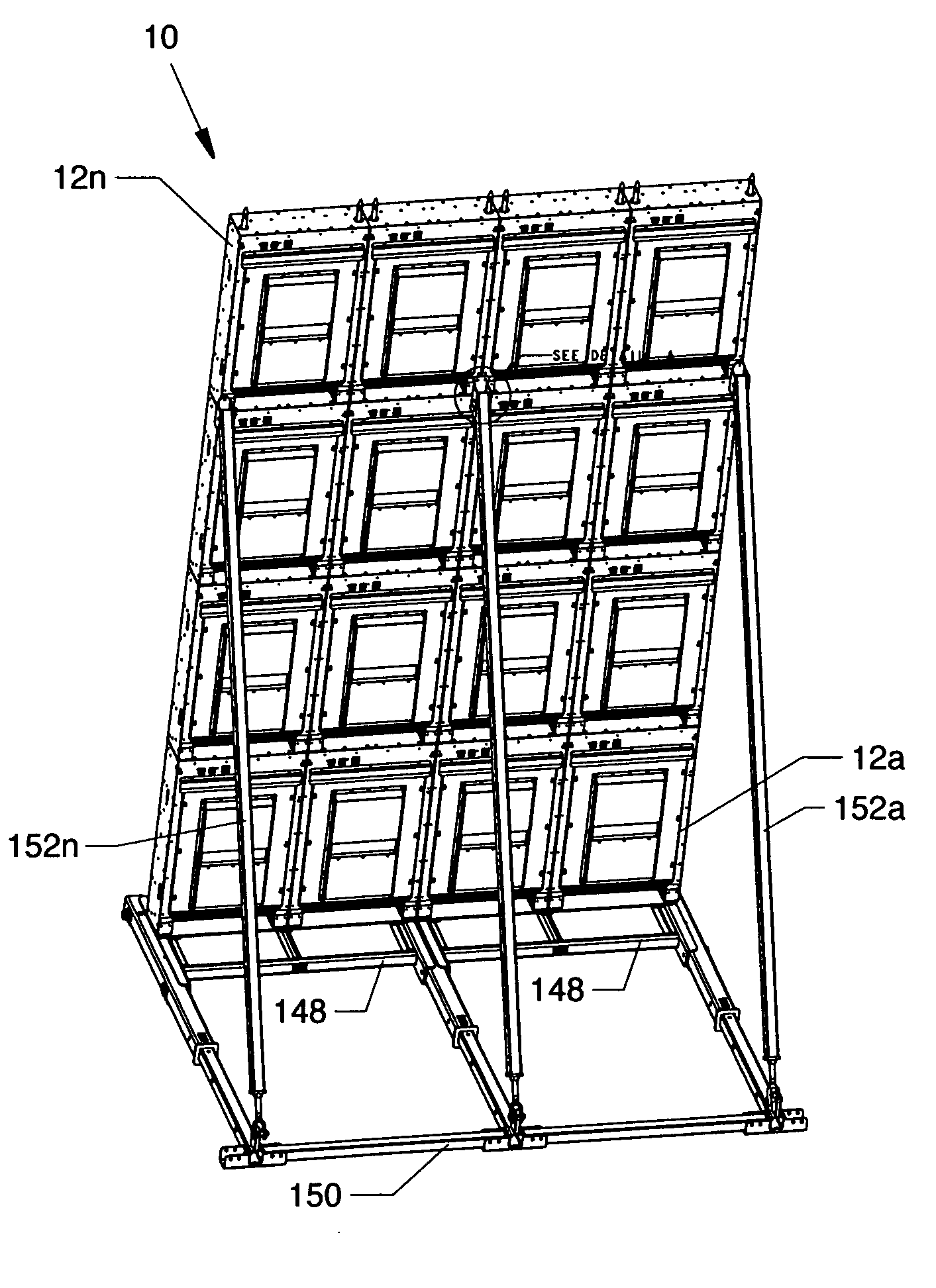
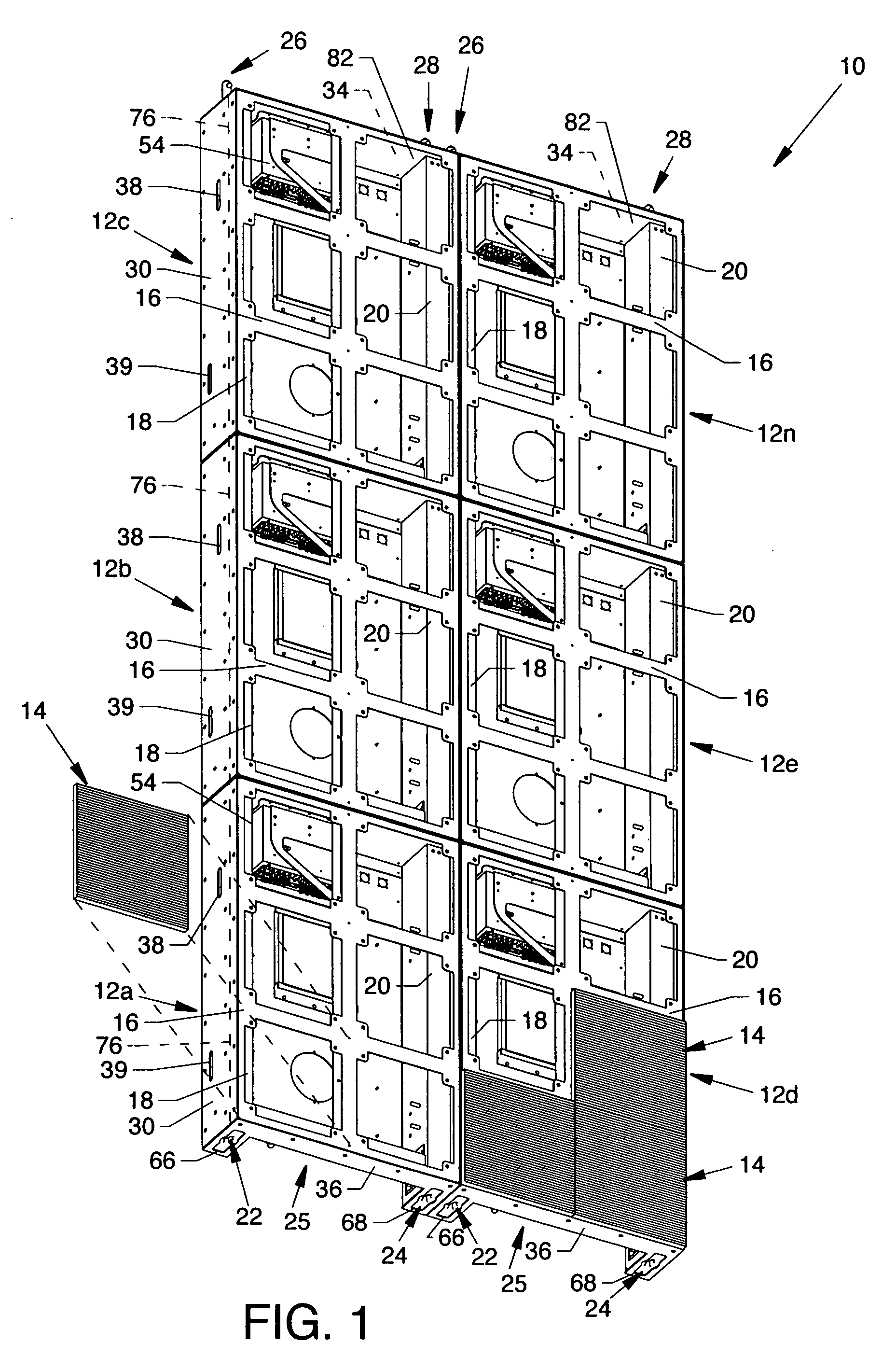
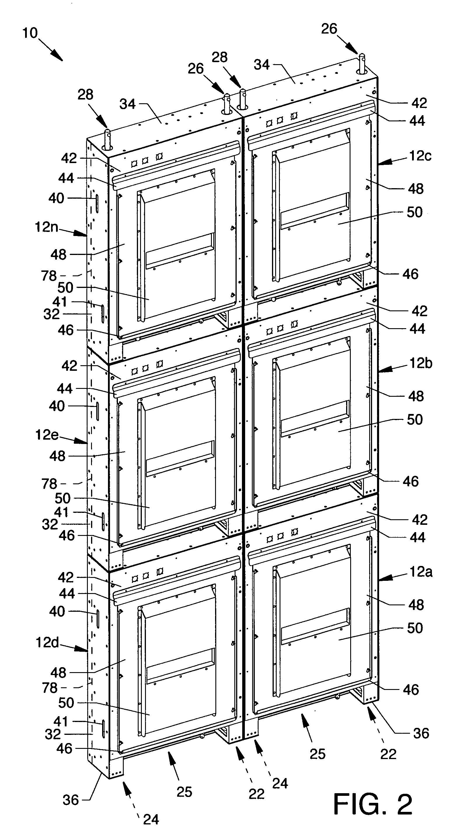
[0032]FIG. 1 is a partially exploded isometric front view of a transportable electronic sign display system 10, and FIG. 2 is an isometric rear view of the transportable electronic sign display system 10 each showing components of the present invention. The invention is comprised of a plurality of stacked modular cabinets 12a-12n where each modular cabinet 12a-12n is made of a light weight material such as aluminum or other suitable light weight material, including a plurality of electronic display modules 14. For the purpose of brevity and clarity, only four electronic display modules 14 are shown in FIG. 1. Each of the modular cabinets 12a-12n includes a mounting panel 16 for accommodation of a plurality of the electronic display modules 14 where the electronic display modules 14, mounting panel 16 and the four-point latching system are described in U.S. Pat. No. 7,055,271 entitled “Electronic Display Module Having a Four-Point Latching System for Incorporation into an Electronic ...


PUM


Abstract

A transportable electronic sign display system having modular cabinets which support electronic display modules and electronics having male and female latching assemblies connecting adjacent electronic display modules. Robust male and female latching assemblies at the top and bottom of electronic display modules provide for forcible positive action latching between vertically situated electronic display modules to provide a minimally visible horizontally oriented seam therebetween. Side latches between horizontally situated electronic display modules assemblies provide for latching to provide a minimally visible vertically oriented seam therebetween.

Description

CROSS REFERENCES TO RELATED APPLICATIONS[0001]This patent application is also related to patent application Ser. No. 10 / 688,304 filed Oct. 17, 2003, entitled “Electronic Display Module Having a Four-Point Latching System for Incorporation into an Electronic Sign and Process,” which is now U.S. Pat. No. 7,055,271, and is incorporated herein by reference.BACKGROUND OF THE INVENTION[0002]1. Field of the Invention[0003]The present invention is for a transportable electronic sign display system, and more particularly relates to a transportable electronic sign display system having latch assemblies which mutually secure modular cabinets of the transportable electronic sign display system to one another.[0004]2. Description of the Prior Art[0005]Prior art methods of attaching transportable electronic sign system display cabinets required a high degree of accuracy in placing the cabinets upon or next to each other, especially along the horizontally oriented top and bottom plates or panels b...

Claims


Application Information

Patent Timeline
IPC IPC(8): G09F15/02
CPCG09F9/30G09F9/33Y10T403/7009G09F15/0056G09F9/3026G09F15/0012Y10T292/1039
Inventor NEARMAN, NATHAN L.DENNIS, MARK D.MILLER, KENT S.HAGE, JOHN
Owner DAKTRONICS
Why Eureka
Try Eureka