Header height sensor apparatus for a header of an agricultural harvester

Inactive Publication Date: 2008-10-30
CNH IND AMERICA LLC
View PDF14 Cites 13 Cited by
  • Summary
  • Abstract
  • Description
  • Claims
  • Application Information

AI Technical Summary

Benefits of technology

[0013]According to another preferred embodiment of the invention, the mounting brackets are connected to the frame of the header in a manner to automatically align the bearings. This can utilize, for instance, a self-aligning carriage bolt or the like. In this way, the variances in the frame and sensor rod are accommodated by the bearings, to allow the sought afte

Problems solved by technology

And, correction of the problem will result in downtime, expense and additional problems.
In this latter regard, some known sensor rods require two persons to install (one on the

Method used


Image

  • Header height sensor apparatus for a header of an agricultural harvester
  • Header height sensor apparatus for a header of an agricultural harvester
  • Header height sensor apparatus for a header of an agricultural harvester

Examples


Example

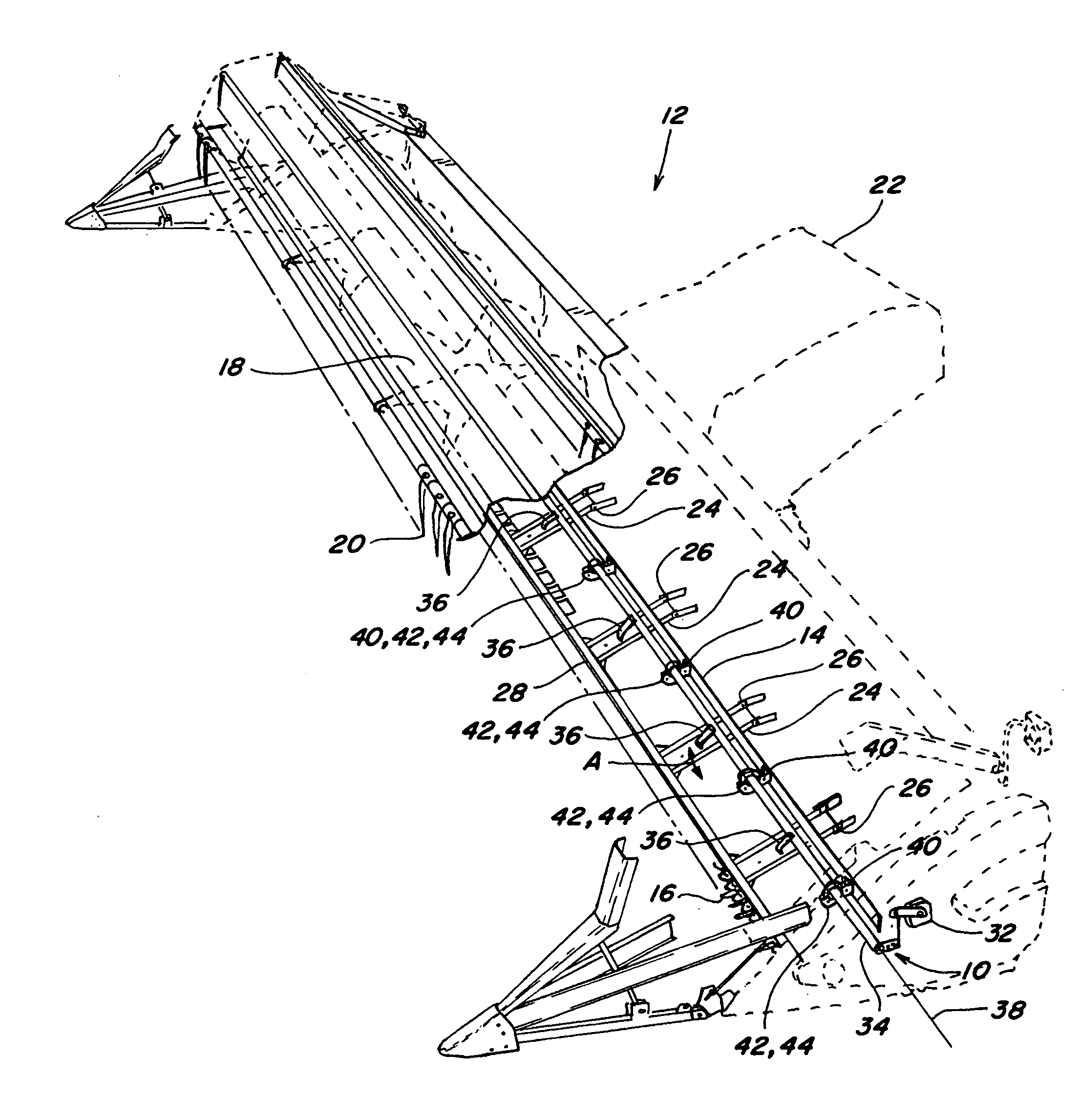
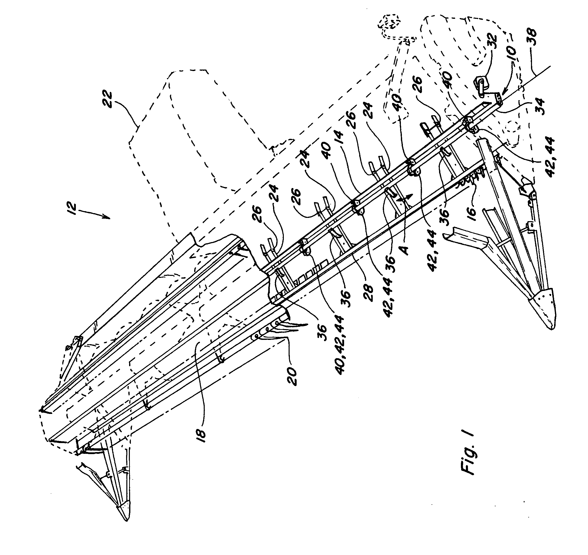
[0020]Referring now to the drawings, in FIGS. 1 and 2, a header height control sensor apparatus 10 constructed and operable according to the teachings of the present invention, is shown incorporated on a header 12 for an agricultural harvester (not shown).

[0021]Header 12 is of generally conventional construction, including an elongate frame 14 supporting cutting apparatus 16 along a front edge thereof, which cutting apparatus 16 in this embodiment comprises a conventionally constructed sickle reciprocatingly operable in the well-known manner for severing crops from a field as header 12 is moved forwardly thereover. Header 12 includes a floor 18 (underside shown in FIG. 2) extending rearwardly from cutting apparatus 16, and onto which the crops will be conveyed by a reel 20, also in the well-known manner. The crops will then be conveyed toward the center of the header by additional conveyor apparatus, e.g., auger or draper belt (not shown), for induction into a feeder 22 which will c...


PUM


Abstract

A plurality of elongate mounting brackets mounted in cantilever relation on a frame of a header at sidewardly spaced locations across at least a portion of a width of the header, respectively, support a sensor rod for rotation about its axis. Each of the brackets has a free end including a bearing having a bore therethrough which receives the sensor rod, at least some of the bearings being self-aligning bearings. The self-aligning capability enables accommodating irregularities in the mounting locations for the brackets, and also bends, flexure and other deformities of the header frame and sensor rod, for achieving free rotatability of the sensor rod. This mounting arrangement also facilitates installation by one person, from the bottom side of the header, both initially and in the field. Additionally, the brackets can include features for aligning the bores of the bearings, to facilitate the installation and free rotation of the sensor rod when installed.

Description

[0001]This application claims the benefit of U.S. Provisional Application No. 60 / 926,873, filed Apr. 30, 2007.TECHNICAL FIELD[0002]This invention relates generally to a sensor apparatus for a header height control for an agricultural harvester, and more particularly, to an improved sensor apparatus including a mounting arrangement for a rotatable sensor rod extending across at least a portion of the header that facilitates installation and free rotation of the rod, for improved sensor operation, including when a sensor rod is bent or deformed, for instance, as a result of contact with rocks or other foreign objects on a field, or the rod and / or the header is flexed.BACKGROUND ART[0003]U.S. Provisional Application No. 60 / 926,873, filed Apr. 30, 2007, is incorporated herein in its entirety by reference.[0004]Header height controls which utilize a sensor having an elongate sensor rod which extends along all or a substantial portion of the sideward width or extent of a header, are well ...

Claims


Application Information

Patent Timeline
IPC IPC(8): A01D47/00A47H1/14A01D41/127
CPCA01D41/141A01D75/18
Inventor DITCHCREEK, BENJAMIN W.NOLL, BLAINE R.MCILWAIN, IRWIN D.
Owner CNH IND AMERICA LLC
Why Eureka
Try Eureka