Apparatus for Measuring an Internal Dimension of a Well Bore
- Summary
- Abstract
- Description
- Claims
- Application Information
AI Technical Summary
Benefits of technology
Problems solved by technology
Method used
Image
Examples
first embodiment
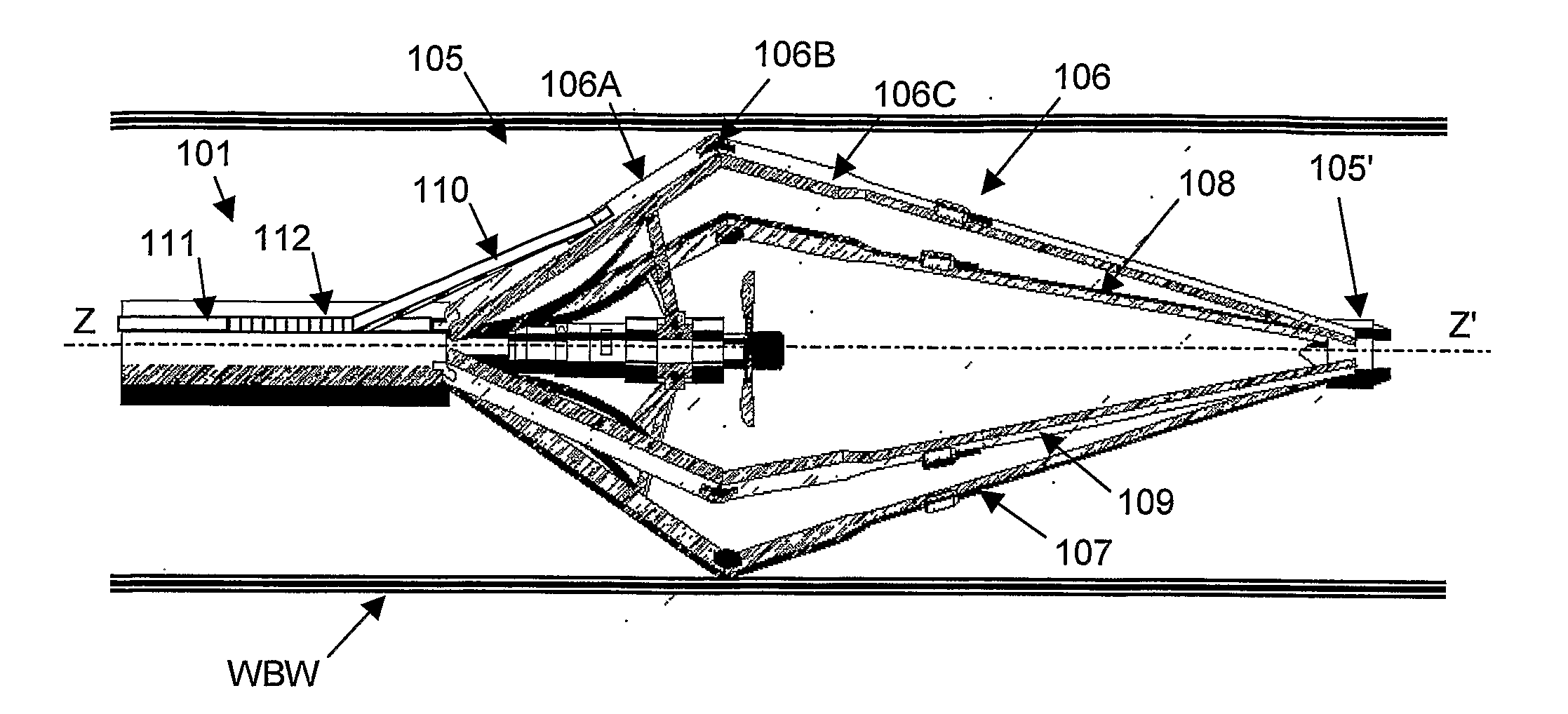
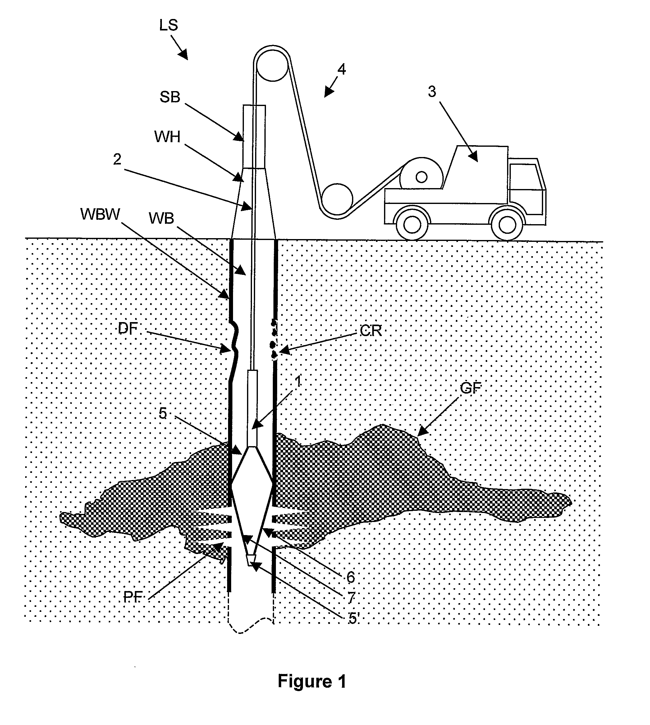
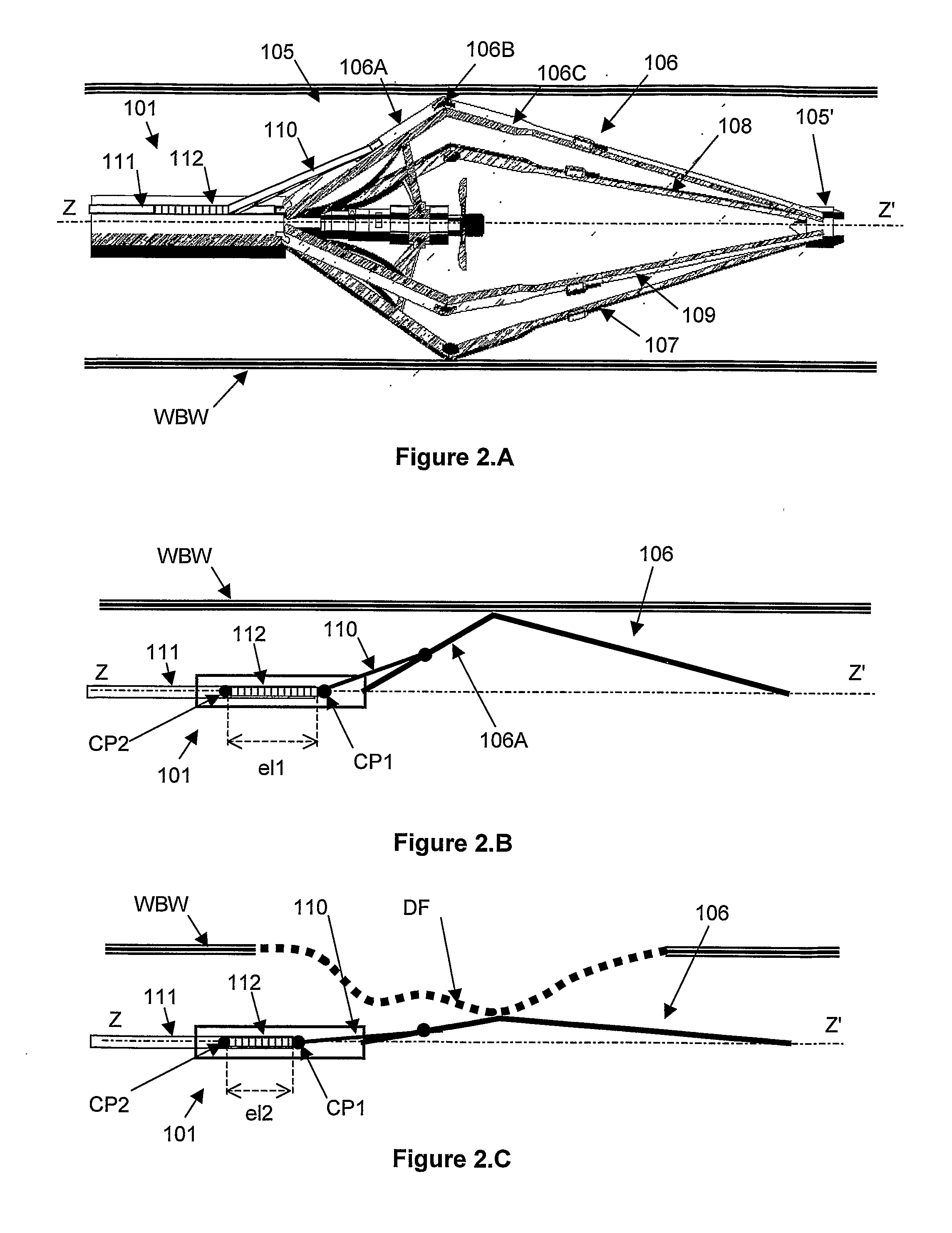
[0047]FIGS. 2.A, 2.B, 2.C and 3 relates to an optical caliper according to the invention.
[0048]The first embodiment of the invention involves an optical sensor in which an incoming light is modulated as a function of the position of a caliper arm. A mechanical movement of the caliper arm induces a modification of the optical response of the optical sensor.
[0049]Advantageously, the optical sensor comprises an optical fiber, a portion of the optical fiber comprising a Bragg grating.
[0050]When coupled to the caliper arms, the optical sensor constitutes a transducer.
[0051]The optical fiber portion comprising the Bragg grating is coupled to the tool (e.g. tool body, the caliper arm) by at least two coupling points encompassing the Bragg grating so that any displacement of the caliper arm induces a modification of the distance between the two coupling points. The distance between the two coupling points is correlated to the position of the caliper arm, thus of the bore-hole dimension. The...
second embodiment
[0075]FIG. 5 schematically illustrates the optical sensor according to the invention.
[0076]The second embodiment of the invention involves an optical sensor in which the absorption of a light beam traveling into an absorbing fluid depends on the position of a caliper arm.
[0077]In a way analogous to the one described in relation with FIGS. 2, the radial displacement of a caliper arm 306 in contact with an internal wall of the well-bore (not shown) is transformed into a translation displacement by an additional arm 310.
[0078]The optical sensor comprises a sealed housing 312 fill with a light absorbing fluid 312′ and coupled to an optical fiber 311A. The sealed housing 312 is positioned within the logging tool. The additional arm 310 is coupled with the sealed housing 312, an extremity of the arm penetrating into the sealed housing. The additional arm comprises a mirror 313A at an extremity in contact with the light absorbing fluid 312′, the mirror facing an optical fiber extremity 311...
third embodiment
[0093]FIG. 6 schematically illustrates the optical sensor according to the invention.
[0094]The third embodiment of an optical caliper according to the invention involves an optical sensor emitting a light beam towards the well-bore wall and measuring a position of the reflected light beam on a space sensitive photo-detector.
[0095]The optical caliper comprises a window 402. The window 402 is made in a wall of the tool 401. The window may be substantially parallel to an internal wall of the well-bore WBW.
[0096]The optical caliper further comprises a reflecting element 403 coupled with an optical fiber 411 through a collimating element 412. The optical caliper emits a collimated light beam in direction to the internal wall of the well-bore with a particular angle α (by convention angle α is the angle existing between the light beam and a perpendicular to the well-bore wall) through the window. The light beam is reflected by the well-bore wall towards the window 402. The optical caliper...
PUM
 Abstract
Description
Claims
Application Information
 - R&D Engineer
- R&D Manager
- IP Professional
- Industry Leading Data Capabilities
- Powerful AI technology
- Patent DNA Extraction
Browse by: Latest US Patents, China's latest patents, Technical Efficacy Thesaurus, Application Domain, Technology Topic.
© 2024 PatSnap. All rights reserved.Legal|Privacy policy|Modern Slavery Act Transparency Statement|Sitemap


