
Eureka
For R&D, Eureka makes reading and utilizing patents & technical documents easy.
Eureka AIR
Designed for self-driven R&D workflows. Generate viable solutions, solve complex R&D challenges, empower your innovation with AI.

Eureka Materials
Designed for material experts only. Revolutionize your material R&D, from search, analyze, to developing new materials.

TechResearch
Generate reliable direction feasibility study reports for your R&D in just a few steps.

TechSeek
Discover and master advanced knowledge NOW. Basics, ideas, possibilities, all at once.

TechMind
As an expert in R&D Theories, TechMind can generates customized viable solutions instantly.

TechRisk
Analyze your overall solution with one click, know your potential R&D risks in advance.

TechMonitor
Get weekly tech updates, stay abreast of the latest tech innovations and key insights.
Wire stripping back bar knife
- Summary
- Abstract
- Description
- Claims
- Application Information
AI Technical Summary
Benefits of technology
Problems solved by technology
Method used
Image

Examples
Embodiment Construction
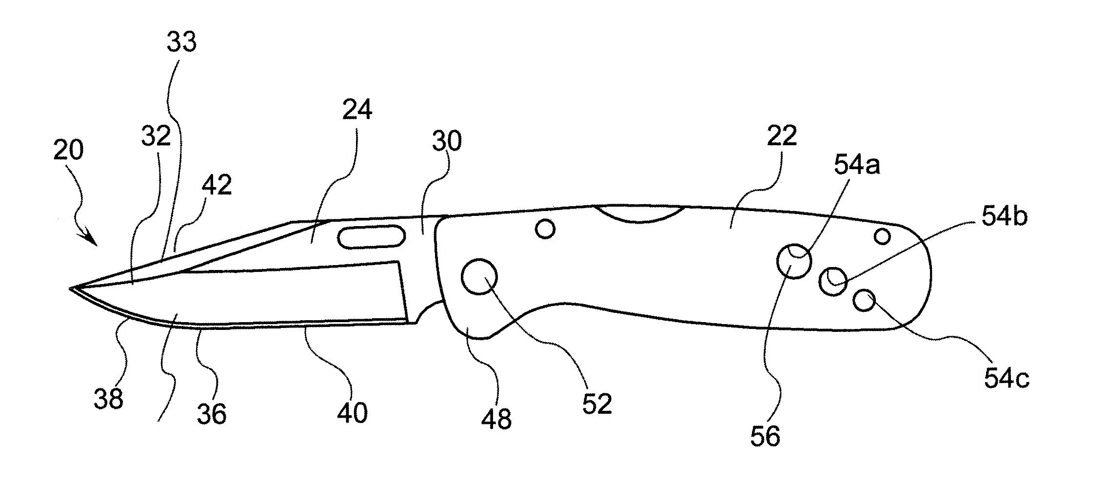
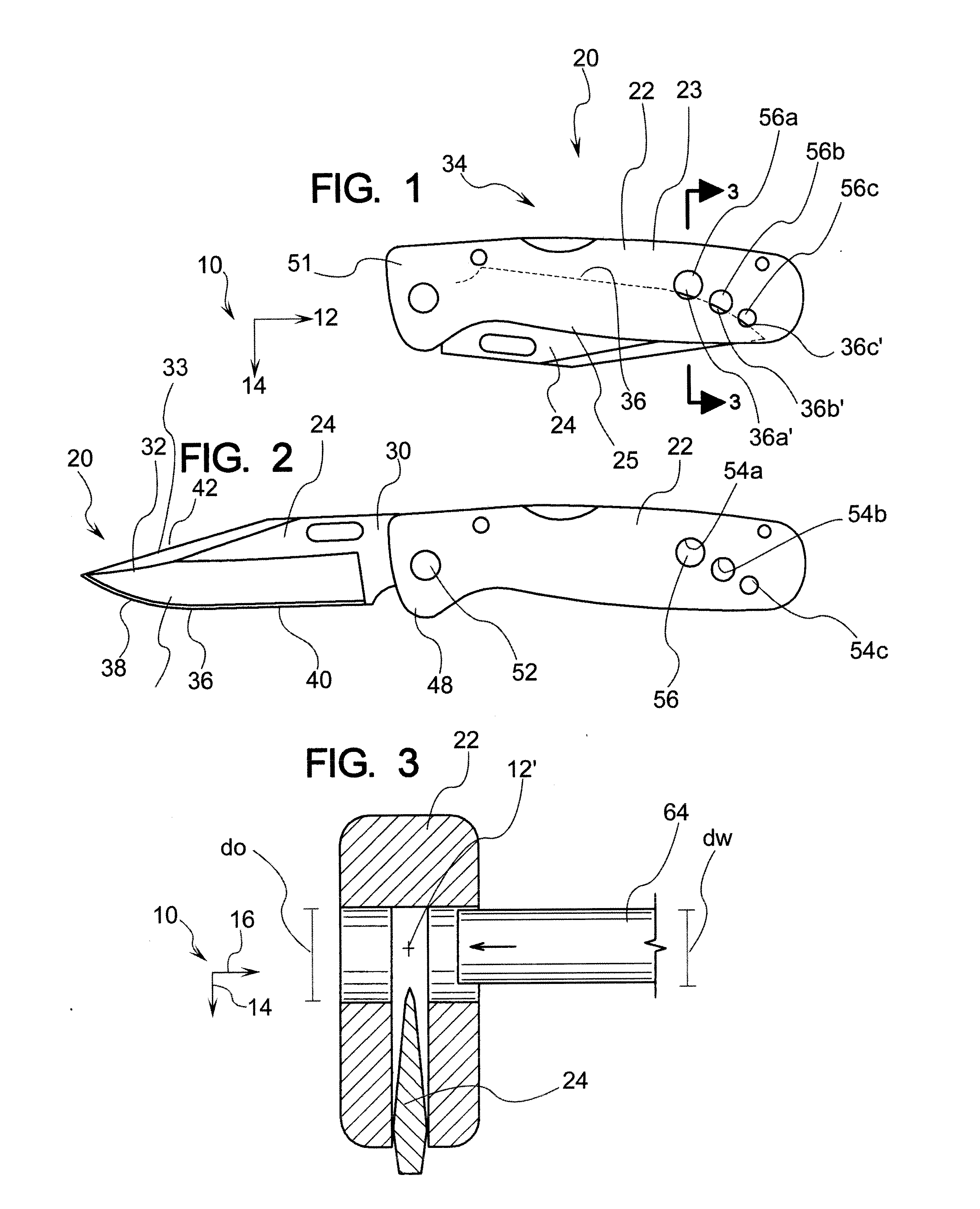
[0046]As shown in FIG. 1, there is a knife 20 comprising a main body / handle portion 22 and a blade 24. To aid in the description of the knife, an axes system is defined indicated at 10 where the axis 12 indicates a longitudinal axis and the axis 14 indicates a transverse axis. Referring now to FIG. 3, you can see that the axis 10 comprises a lateral axis 16. In general, the center longitudinal axis indicated at 12′ as shown in FIG. 3 indicates a middle portion of the knife, where extending laterally in the direction 16 from the center axis 12′ indicates laterally outward directions with respect to the knife 20.
[0047]Referring back to FIG. 1, it can be seen how the knife 20 is in a folded closed orientation. FIG. 2 shows the blade in an open configuration. In general, the folding knife 20 is a locking knife in most forms where the knife will lock in an open orientation. In general, the blade 24 comprises a base region 30 and a forward portion 32. The blade locking system 34 is of a g...
PUM
| Property | Measurement | Unit |
|---|---|---|
| Diameter | aaaaa | aaaaa |
| Size | aaaaa | aaaaa |
| Metallic bond | aaaaa | aaaaa |
Abstract
Description
Claims
Application Information
 - R&D Engineer
- R&D Manager
- IP Professional
- Industry Leading Data Capabilities
- Powerful AI technology
- Patent DNA Extraction
Browse by: Latest US Patents, China's latest patents, Technical Efficacy Thesaurus, Application Domain, Technology Topic, Popular Technical Reports.
© 2024 PatSnap. All rights reserved.Legal|Privacy policy|Modern Slavery Act Transparency Statement|Sitemap|About US| Contact US: help@patsnap.com