Pnuematic tire

a technology of pneumatic tires and tires, applied in the field of pneumatic tires, can solve the problems of conflicting goals, and achieve the effect of improving traction and excellent wet performan

Inactive Publication Date: 2008-11-06
MORRISON ANDREW EDWARD +4
View PDF9 Cites 27 Cited by
  • Summary
  • Abstract
  • Description
  • Claims
  • Application Information

AI Technical Summary

Benefits of technology

[0004]The present invention is directed to a tire with a tread designed for achieving the goals of enhanced traction with excellent wet performance.

Problems solved by technology

However, since enhanced traction is best achieved by providing most biting edges to the tread pattern, while road contact is achieved by providing more surface area for tread contact, these goals are often conflicting.

Method used


Image

  • Pnuematic tire
  • Pnuematic tire
  • Pnuematic tire

Examples


Embodiment Construction

[0021]The following language is of the best presently contemplated mode or modes of carrying out the invention. This description is made for the purpose of illustrating the general principals of the invention and should not be taken in a limiting sense. The scope of the invention is best determined by reference to the appended claims.

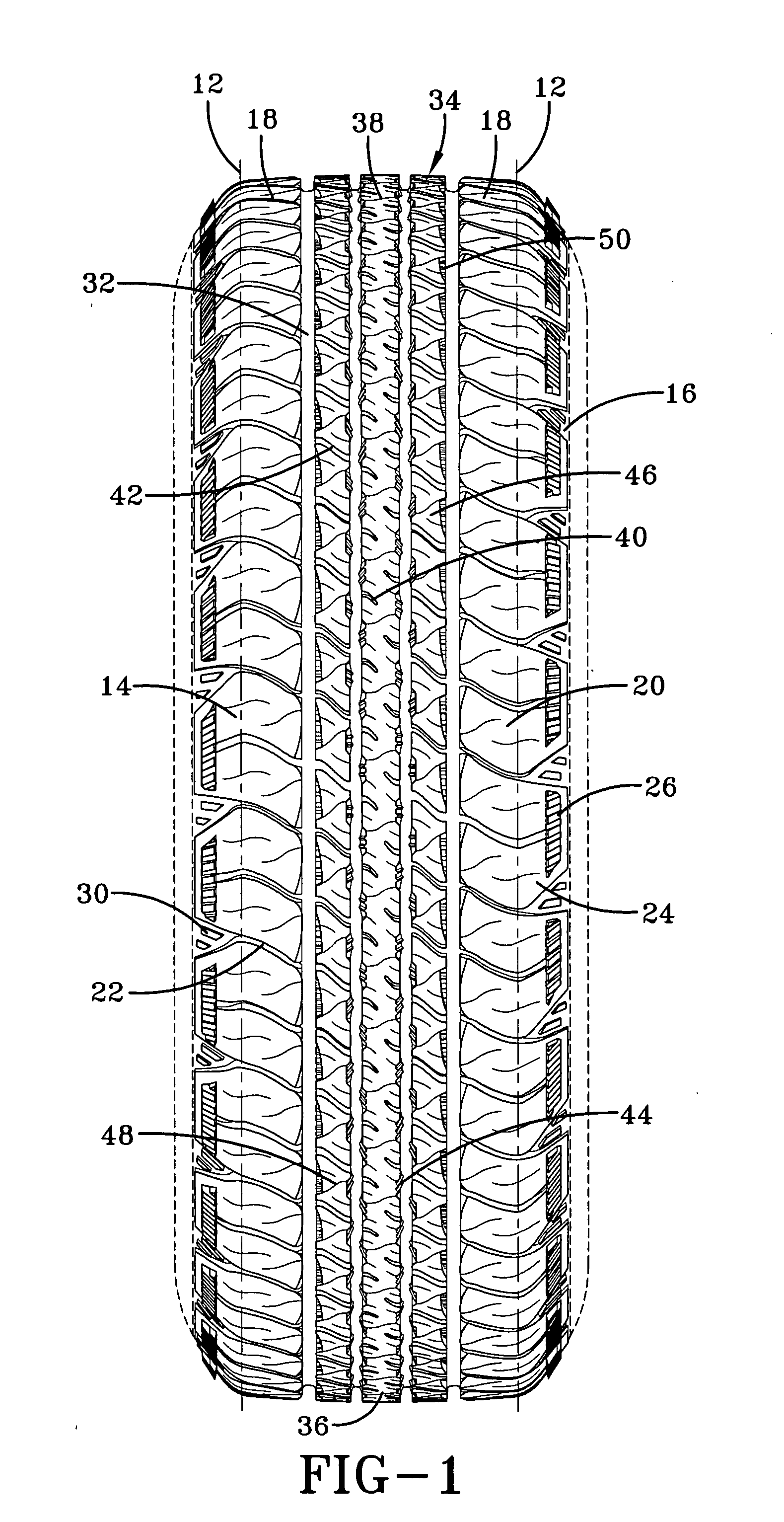
[0022]FIG. 1 is a tire with a tread and shoulders in accordance with the present invention. The tire has a tread 10 located between a pair of opposing tread edges 12; axially outward of the tread edges 12 are the opposing tire shoulders 14. The shoulders 14 extend into and merge with the tire sidewalls 16. The illustrated tread 10 is intended for use on a passenger vehicle tire or a light truck tire, but features in the tread may be used individually or collectively for these or other types of tires. The tread 10 has a pair of opposing outer tread rows 18, each outer tread row having circumferentially adjacent blocks 20 separated by lateral grooves 22. ...


PUM


Abstract

The tire has a ground contacting tread portion, the tread comprising at least one straight circumferentially extending groove. The groove defines one lateral side and a lateral boundary of a plurality of tread elements. At least one tread element has a chamfer within the tread element and inward of the lateral boundary of the tread element. The chamfer extends in the circumferential direction of the tire and has an inclined radially outer surface. The chamfer has at least one traction element in the radially outer surface, the indentation extending radially inward of the radially outer surface of the chamfer.

Description

FIELD OF THE INVENTION[0001]The present invention is directed to a pneumatic tire. More specifically, the present invention is directed to a pneumatic tire with improved water and traction characteristics.BACKGROUND OF THE INVENTION[0002]In a conventional tire for typical use as on a passenger car or light truck, the tire tread is provided with a series of grooves, either circumferentially or laterally extending, or a combination of both, to form a plurality of blocks.[0003]The goals of a tire during winter driving condition are to maintain good contact with the road, while providing for enhanced traction. However, since enhanced traction is best achieved by providing most biting edges to the tread pattern, while road contact is achieved by providing more surface area for tread contact, these goals are often conflicting.SUMMARY OF THE INVENTION[0004]The present invention is directed to a tire with a tread designed for achieving the goals of enhanced traction with excellent wet perfo...

Claims


Application Information

Patent Timeline
Patent Type & Authority Applications(United States)
IPC IPC(8): B60C11/13
CPCB60C11/01B60C11/0306B60C11/0309B60C11/032B60C11/1392B60C2011/1338
Inventor MORRISON, ANDREW EDWARDRENNER, LEYLA KRISTENKANTURA, JOHN JOSEPHMAXWELL, PAUL BRYANSHONDEL, JONATHAN JAMES
Owner MORRISON ANDREW EDWARD
Why Eureka
Try Eureka