Light emitting diode assembly and light emitting diode display device

a technology of light-emitting diodes and assembly, which is applied in the direction of identification means, sustainable manufacturing/processing, instruments, etc., can solve the problems of time-consuming and labor-intensive distinguising between the positive and the negative electrodes, and achieve the effect of reducing the number of times of b>912/b>

Inactive Publication Date: 2008-11-13
FOXSEMICON INTEGRATED TECH INC
View PDF3 Cites 34 Cited by
  • Summary
  • Abstract
  • Description
  • Claims
  • Application Information

AI Technical Summary

Benefits of technology

[0010]Detailed features of the present LED assembly and LED display device will become more apparent from the following detailed description and claims, and the accompanying drawings.

Problems solved by technology

However, distinguishing between the positive and the negative electrodes 911, 912 is time consuming.

Method used


Image

  • Light emitting diode assembly and light emitting diode display device
  • Light emitting diode assembly and light emitting diode display device
  • Light emitting diode assembly and light emitting diode display device

Examples


Embodiment Construction

[0022]Reference will now be made to the drawings to describe the preferred embodiments of the light emitting diode (LED) assembly and the LED display device, in detail.

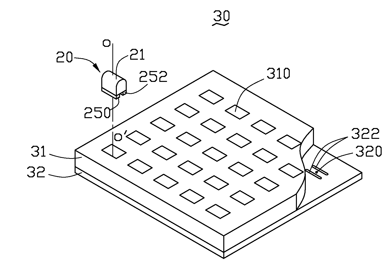
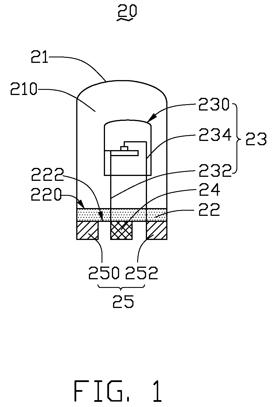
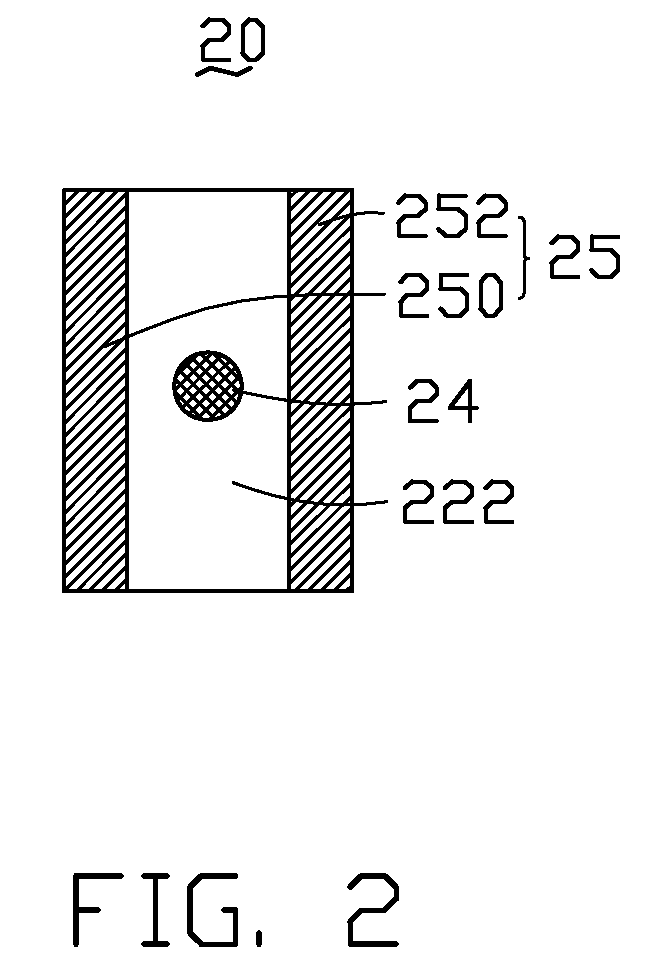
[0023]Referring now particularly to FIGS. 1 and 2, a LED assembly 20, according to a first exemplary embodiment, is provided. The LED assembly 20 includes a cover 21, a substrate 22, a LED unit 23, a first electrode terminal 24 and a second electrode terminal 25.

[0024]The cover 21 is suitably made of light transmissive materials such as plastic, resin and glass.

[0025]The substrate 22 is a glass fiber board, a flexible printed circuit board or a ceramic board. The substrate 22 includes a first surface 220 and a second surface 222 on an opposite side of the substrate 22 to the first surface 220. The first surface 220 and the cover 21 cooperatively define a cavity 210.

[0026]The LED unit 23 may be a LED lamp such as a surface mount device LED lamp, a chip on board LED lamp, and a lead frame LED lamp. In the illustrated em...


PUM


Abstract

An exemplary light emitting diode (LED) assembly includes a cover, a substrate, a LED unit, a first electrode terminal, and a second electrode terminal. The substrate includes a first surface and a second surface on an opposite side of the substrate thereto. The substrate and the cover cooperatively define a cavity. The LED unit is received in the cavity. The first and the second electrode terminals extend from the second surface. The first electrode terminal is electrically connected to one of a positive lead and a negative lead of the LED unit and the second electrode terminal is electrically connected to the other. The second electrode terminal includes a first electrode portion and a second electrode portion symmetrically arranged at opposite sides of the first electrode terminal. The first and the second electrode portions are at least partially symmetrical with respect to the first electrode terminal.

Description

BACKGROUND[0001]1. Technical Field[0002]The present invention relates to light emitting diode assemblies and light emitting diode display devices.[0003]2. Discussion of Related Art[0004]Light emitting diode (LED) assemblies having various sizes and display effects have been developed and are available in the market. Depending on the complexity of the required illumination pattern, most LED display devices include a number of LED assemblies arranged in an array and selectively switchable on / off to generate such an illumination pattern.[0005]Referring to FIG. 10, a typical LED display device is provided. The LED display device includes a number of lead-frame LED assemblies 91, a positioning member 92, and a printed circuit board 93. In FIG. 10, only one LED assembly 91 is shown for the purpose of illustration. The LED assemblies 91 each have a positive electrode 911 and a negative electrode 912. The positioning member 92 defines a number of positioning holes 920 penetrating therethrou...

Claims


Application Information

Patent Timeline
Patent Type & Authority Applications(United States)
IPC IPC(8): H01L33/00H01L33/48H01L33/62
CPCG09F9/33H01L33/486H01L33/62H05K3/303H05K3/325H05K2201/083H05K2201/10106H05K2201/10636H05K2203/0186H05K2203/167H05K2203/168H01L2924/0002H01L2924/00Y02P70/50
Inventor KUO, KUN-SHENGYANG, CHUAN-FUCHU, YUAN-FA
Owner FOXSEMICON INTEGRATED TECH INC
Why Eureka
Try Eureka