Motor drive device, image reading device, image forming apparatus, and motor drive method
- Summary
- Abstract
- Description
- Claims
- Application Information
AI Technical Summary
Benefits of technology
Problems solved by technology
Method used
Image

Examples
Example
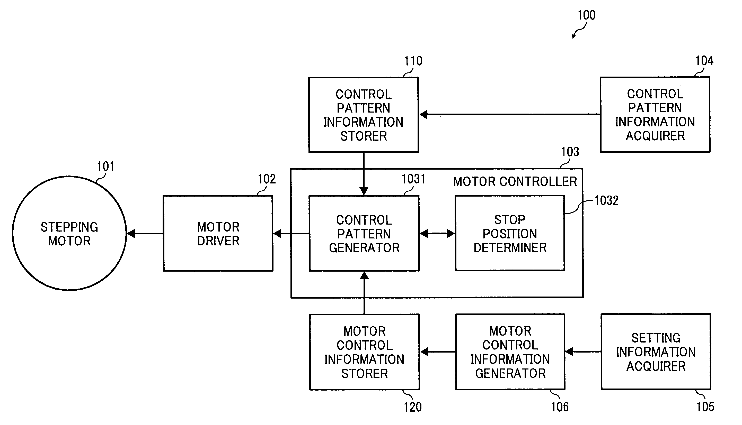
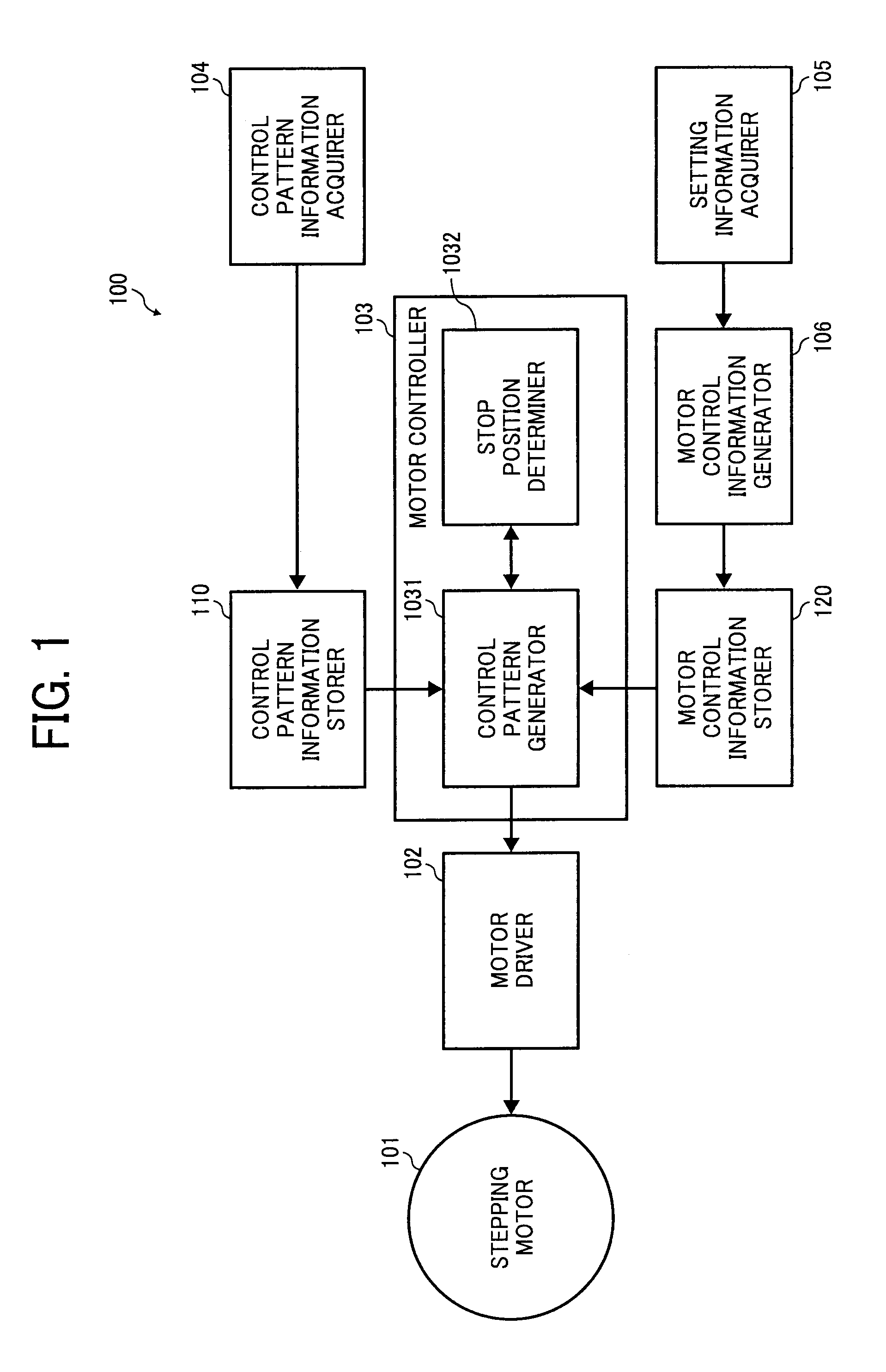
[0096]A motor drive device 200 according to the second embodiment includes a stepping motor 101, a motor driver 102, a motor controller 203, a control pattern information acquirer 104, a setting information acquirer 105, a motor control information generator 106, a control pattern information storer 110, a motor control information storer 120, and an address control information storer 230.
[0097]The structure and functions of the stepping motor 101, the motor driver 102, the control pattern information acquirer 104, the setting information acquirer 105, the motor control information generator 106, the control pattern information storer 110 and the motor control information storer 120 are the same as for the first embodiment and are not described here.
[0098]The address control information storer 230 stores control information used while controlling addresses. FIG. 16 is a view explaining an example data structure for the address control information storer 230 and obtained values. As s...
Example
[0122]A motor drive device 300 according to the third embodiment includes a stepping motor 101, a motor driver 102, a motor controller 303, a control pattern information acquirer 104, a setting information acquirer 105, a motor control information generator 106, a control pattern information storer 110 and a motor control information storer 120. The structure and functions of the stepping motor 101, the motor driver 102, the control pattern information acquirer 104, the setting information acquirer 105, the motor control information generator 106, the control pattern information storer 110 and the motor control information storer 120 are the same as for the first embodiment and are not described here.
[0123]The motor controller 303 includes a control pattern generator 3031 and the stop position determiner 1032. The structure and function of the stop position determiner 1032 are the same as for the first embodiment and are not described.
Example
[0124]In addition to the functions and structure explained for the first embodiment, the control pattern generator 3031 sends a position flag to the stop position determiner 1032 while sending a control pattern corresponding to a position corresponding to the excitation mode operated at next stored in the motor control information storer 120 to the motor driver 102. It is then possible to determine a position corresponding to the excitation mode operated at next as the stop position at the stop position determiner 1032.
[0125]Next, motor drive control processing by the motor control unit of the above structure is explained. FIG. 23 is a flowchart of a motor drive control processing procedure carried out by the motor control unit. The motor drive control processing procedure of this embodiment is substantially the same as the flowchart of FIG. 8 and only different portions are explained. Step S2301 to Step S2309, and Step S2312 to Step S2315 are referred to in the explanation of FIG. ...
PUM
 Abstract
Description
Claims
Application Information
 - R&D Engineer
- R&D Manager
- IP Professional
- Industry Leading Data Capabilities
- Powerful AI technology
- Patent DNA Extraction
Browse by: Latest US Patents, China's latest patents, Technical Efficacy Thesaurus, Application Domain, Technology Topic.
© 2024 PatSnap. All rights reserved.Legal|Privacy policy|Modern Slavery Act Transparency Statement|Sitemap