
Combined transformer

Inactive Publication Date: 2008-11-13
DELTA ELECTRONICS INC
View PDF2 Cites 15 Cited by
  • Summary
  • Abstract
  • Description
  • Claims
  • Application Information

AI Technical Summary

Problems solved by technology

Normally, electronic devices comprise a plurality of transformers therein, thus, the sizes of the electronic devices using the plurality of transformers are not easily shrunk.

Method used


Image

  • Combined transformer
  • Combined transformer
  • Combined transformer

Examples


Embodiment Construction

[0013]The following description is of the best-contemplated mode of carrying out the invention, this description is made for the purpose of illustrating the general principles of the invention and should not be taken in a limiting sense. The scope of the invention is best determined by reference to the appended claims.

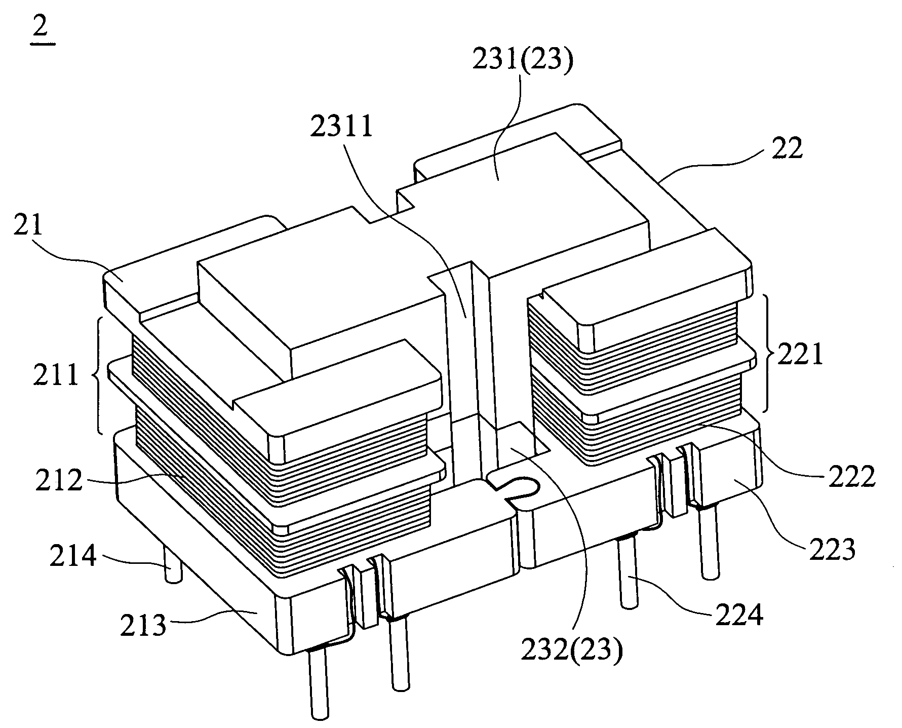
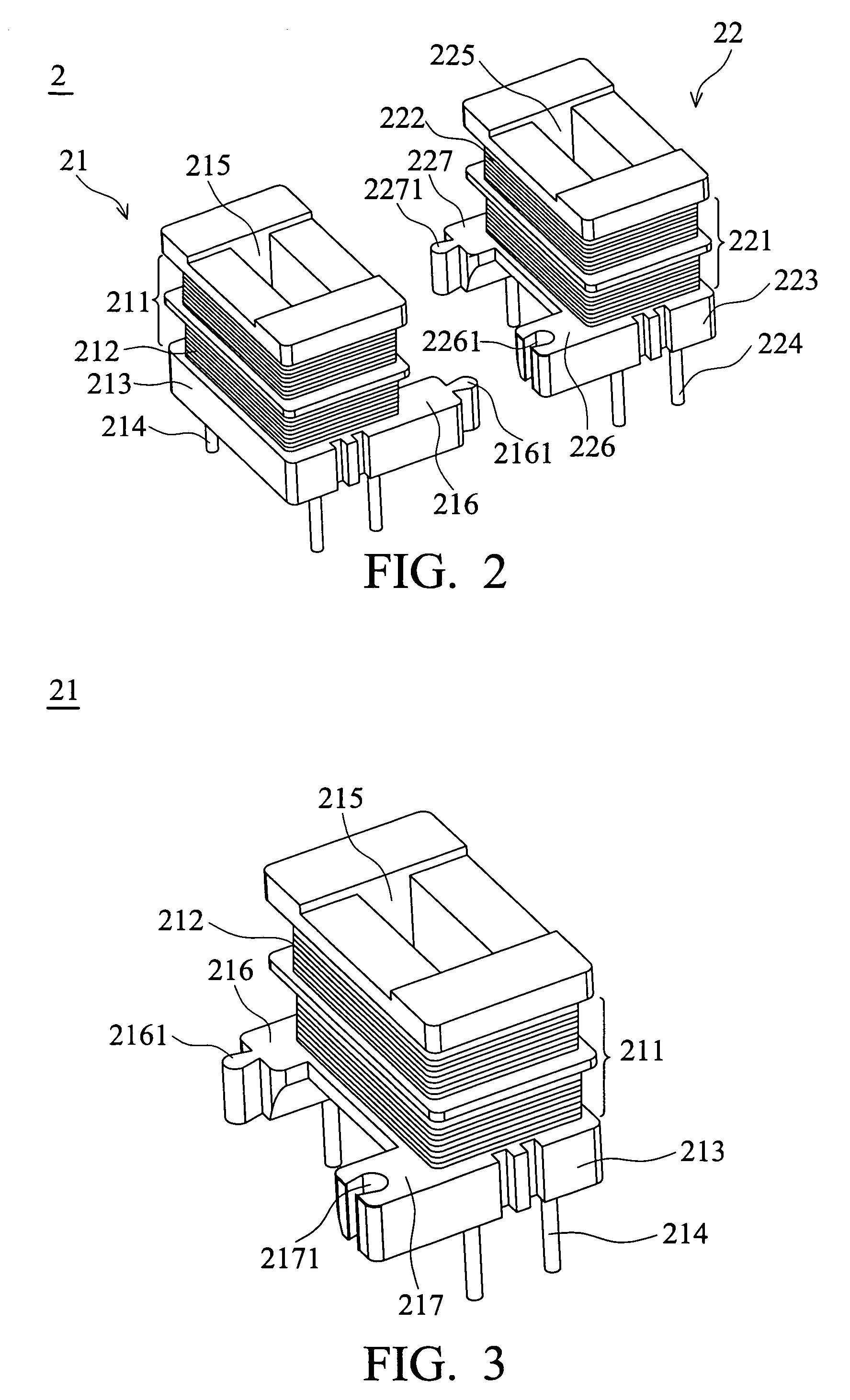
[0014]Referring to FIGS. 2, 3, 4 and 5 a combined transformer 2 of an embodiment includes a first bobbin 21, a first base 213, a second bobbin 22, a second base 223, and an iron core set 23. The combined transformer 2 is applied to an electronic device. In this embodiment, the transformer 2 is a vertical transformer or a high-frequency transformer.

[0015]The first and second bobbins 21, 22 include winding regions 211 and 221, respectively. At least an enameled wire is wound on the winding regions 211 (221) to form a winding 212(222). The windings 212 and 222 act as a primary winding and a secondary winding of the transformer 2. The first and second bobbins 21, 22 both i...


PUM


Abstract

A transformer includes a first bobbin, a second bobbin, and an iron core set, wherein the first bobbin and the second bobbin further include a winding region and a through hole in the center of the bobbin, respectively. The winding region is wound by a winding. The iron core set is coupled to the first and second bobbins. The first and second bobbins are assembled together by a base.

Description

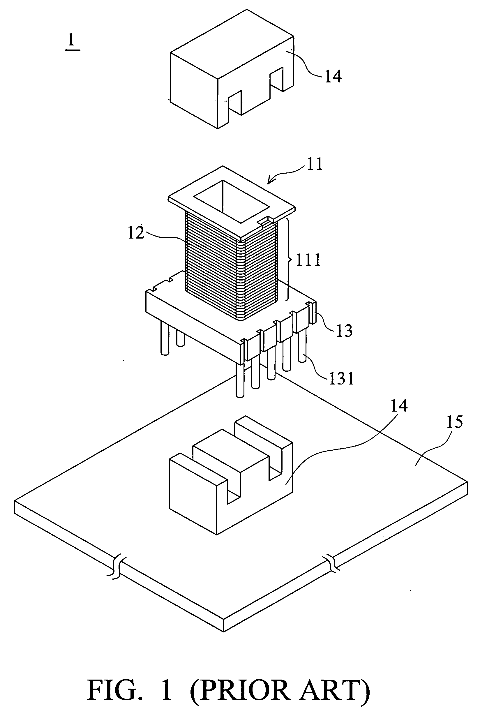
BACKGROUND OF THE INVENTION[0001]1. Field of the Invention[0002]The invention relates to a vertical transformer, and more particularly to a vertical transformer structure for combining two transformers.[0003]2. Description of the Related Art[0004]Transformers are an electronic elements usually applied to all types of electronic devices. Referring to FIG. 1, a conventional transformer 1 includes a bobbin 11, a winding assembly 12, a base 13 and two iron cores 14. The winding assembly, 12 includes an enameled wire to wind a winding region 111 of the bobbin 11. The base 13 is connected to the bobbin 11 and includes a plurality of pins 131 electrically connected to a printed circuit board 15. The iron cores 14 are correspondingly disposed, on two sides of the bobbin 11 and coupled each other so that the electromagnetic induction can be generated by the iron cores 14 and the winding assembly 12. The axle of the bobbin 11 is parallel to the pins 131 of the base 13. Thus, the transformer i...

Claims


Application Information

Patent Timeline
IPC IPC(8): H01F27/30
CPCH01F27/06H01F27/266H01F27/306H01F2027/065
Inventor KANG, YING-CHIANHUANG, NENG-KUEIKAO, CHING-MANHSU, HAN-CHENG
Owner DELTA ELECTRONICS INC
Learn More