Eureka AIR delivers breakthrough ideas for toughest innovation challenges, trusted by R&D personnel around the world.

Milk pump

Inactive Publication Date: 2008-11-13
TRIMED
View PDF12 Cites 2 Cited by
  • Summary
  • Abstract
  • Description
  • Claims
  • Application Information

AI Technical Summary

Benefits of technology

[0006]Therefore, it is an object of the invention to design a milk pump of the type mentioned

Problems solved by technology

As far as the displacement space is merely plugged, the interconnection of these parts is, of course, quite unreliable.
In both cases, pumping is rather troublesome; in the first case due to the mere plug connection and the necessity to move a suction membrane upwards, while a cranked actuation lever has to be moved in lateral direction (which leads to friction losses and causes fatigue of the hand); in the second case, because actuating a syringe in two opposite directions requires the use of both hands for pumping, while the milk receptacle has to be held too.
Hose connections, however, should be avoided because of the possibility of an entanglement, because of the difficulty to keep it in hygienic conditions, and also because of the tendency of the resilient material of such hoses to become brittle, crumbling or flawy.
It has been mentioned above that a hose connection is not favorable; however, a screwing connection has also its perils: First removing from a mold during production, e.g. by injection molding, is easy, particular

Method used


Image

  • Milk pump
  • Milk pump
  • Milk pump

Examples


Example

DETAILED DESCRIPTION OF THE DRAWINGS

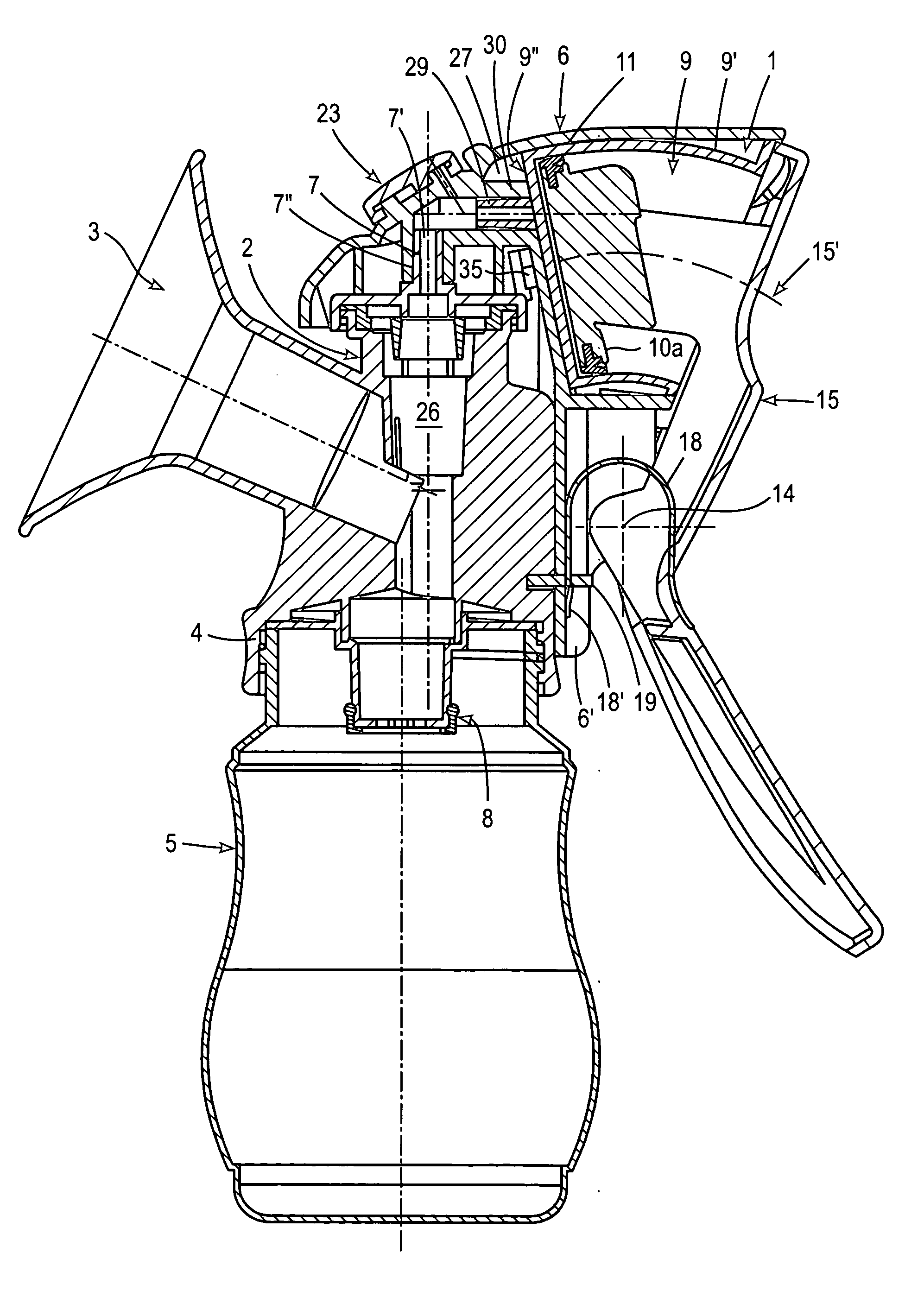
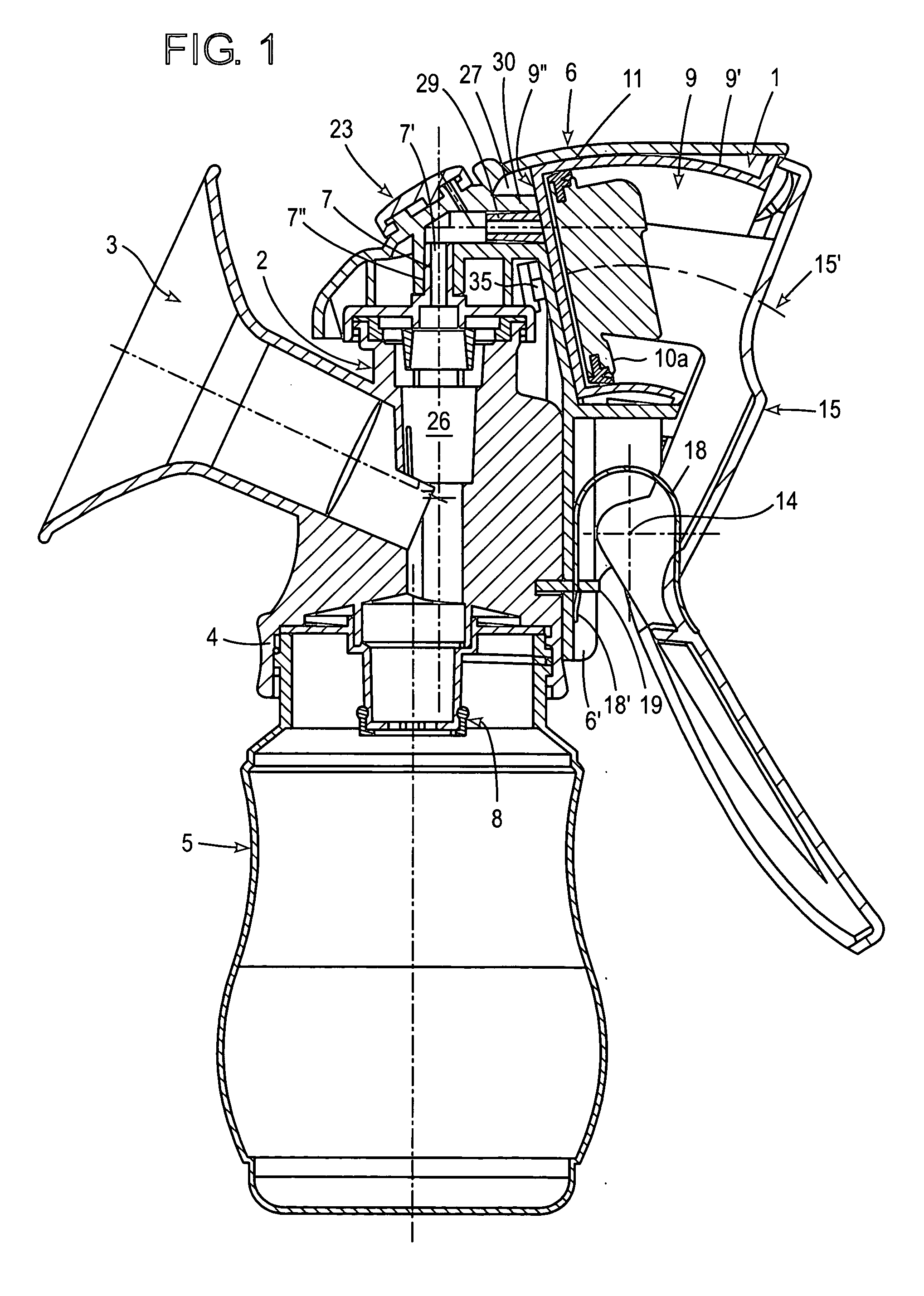
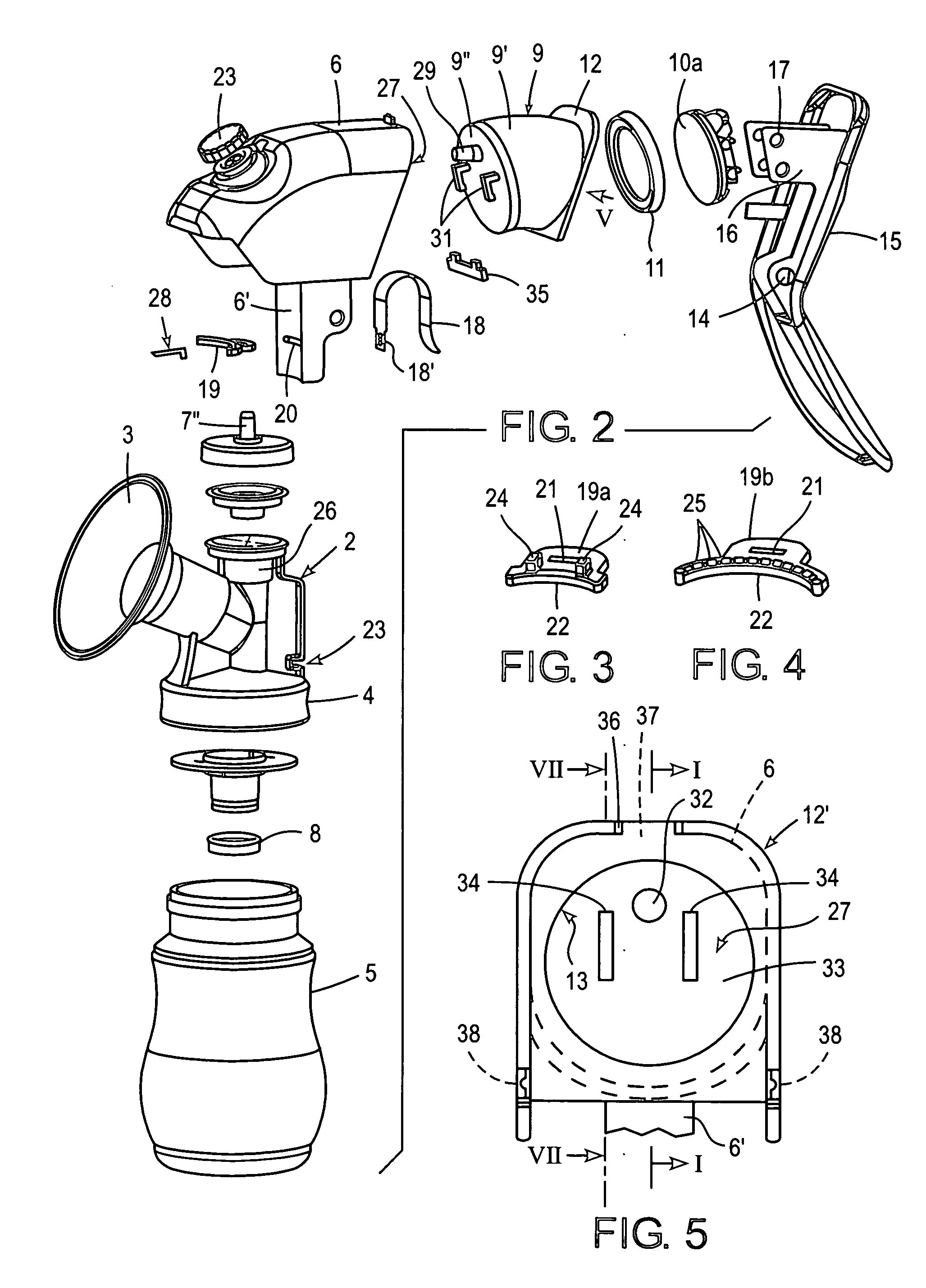
[0026]The milk pump illustrated in FIG. 1 comprises an upper support 6 including a manual pumping unit 1, which is plugged onto a connection piece 2. To this end, the connection piece 2 comprises a pipe socket 7, which extends in upward direction and has a connection opening 7′ onto which a pipe socket 7″ of the support is plugged. The two pipe sockets 7, 7″ are slightly conical so that a tight and firm connection will be established. The support 6, in principle, could be constructed in a variety of shapes and manners, and could, for example, consist of individual bars or strips; however, it is preferred, as illustrated, if it is about cap-shaped, forming a hollow interior where it receives and protects the manual pumping unit 1.

[0027]The connection piece 2, on the one hand, comprises a breast hood 3 or horn, and a threaded part 4, on the other hand, by which the pump may be screwed onto a milk collector receptacle 5. In a known manner, there is a...


PUM


Abstract

A milk pump for pumping milk from a woman's breast comprises a breast hood for receiving tightly a woman's breast. Furthermore, there is a milk collecting arrangement for receiving milk pumped from said woman's breast. This milk collecting arrangement includes a support and a downwards directed opening in the support for providing a suction communication to the breast hood. Moreover, the milk collecting arrangement comprises a manual pumping unit above the said opening. The manual pumping unit includes a wall forming and surrounding a displacement space which comprise a front wall and a peripheral wall extending in longitudinal direction. A suction device is displaceable inside the displacement space to provide suction through the opening, wherein the displacement is provoked by an actuation device. Furthermore, there is a latching arrangement for releasably connecting at least part of the wall of the displacement space to the support for an easy exchange.

Description

FIELD OF THE INVENTION[0001]The present invention relates to milk pumps for pumping milk from a woman's breast. Conventional milk pumps of this kind comprise a breast hood for receiving tightly a woman's breast to draw milk out of it and to collect it first in a milk space from which it flows, mostly over a non-return valve, into a collecting receptacle or bottle. The part of the milk pump, which joins the breast hood, includes normally a support of any shape and design to carry a manual pumping unit above an opening to the milk collecting space so that suction can be exerted by the manual pumping unit through this opening which is a downwards directed in the support for providing a suction communication to the breast hood. This suction communication is necessary for a manual pumping unit above the opening which includes a wall forming and surrounding a displacement space. The displacement space defines a longitudinal axis along which a suction element is moving, be it a piston or a...

Claims


Application Information

Patent Timeline
IPC IPC(8): A61M1/06
CPCA61M1/06A61M2205/073A61M2205/586A61M1/0068A61M1/81
Inventor NUESCH, HANSUELI
Owner TRIMED
Why Eureka
Eureka Blog
Learn More