Radar device and method for adjusting among radar sites

a radar and site technology, applied in the direction of measurement devices, instruments, climate sustainability, etc., can solve the problems of interference, wave affecting the precision of radar signal processing data, and difficult to realize echo signals

Inactive Publication Date: 2008-11-20
KK TOSHIBA
View PDF8 Cites 6 Cited by
  • Summary
  • Abstract
  • Description
  • Claims
  • Application Information

AI Technical Summary

Benefits of technology

[0009]As mentioned above, in the conventional radar device, if pulse repetition frequencies (PRFs) of the interfering stations are close to one another, or if the number of the interfering stations is large, these interference waves affect on the precision of the radar signal processing data. Increasing the effect of the secondary echo reduces the detection precision of the real echo signal. Further, in the case of using a plurality of types of transmission pulse signals, the interference among the pulse signals significantly affect the detection precision of the echo signal.

Problems solved by technology

If a center frequency of the received signal is close If a center frequency of the received signal is close to a center frequency of a transmitted signal, interference occurs.
However, in practice, if pulse repetition frequencies (PRFs) of the interfering stations are close to one another, or if the number of the interfering stations is large, a plurality of interference waves are resulted in continuous receptions and, these interference waves affect the precision of radar signal processing data.
As a related problem, in a radar device emitting transmission signals having a plurality of types of pulse widths and moderation methods, overlapping a secondary echo with a weak real echo signal makes it difficult the real echo signal.
Further, in a radar device using a plurality of types of transmission pulse signals, interference among pulse signals significantly affect the detection precision of the echo signal.
For example, in a pulse compression radar device using a short pulse and a long pulse in the PRF, the short pulse for short range leaks into a long-range area, and it results in reducing the echo detection precision of the long pulse.
As mentioned above, in the conventional radar device, if pulse repetition frequencies (PRFs) of the interfering stations are close to one another, or if the number of the interfering stations is large, these interference waves affect on the precision of the radar signal processing data.
Increasing the effect of the secondary echo reduces the detection precision of the real echo signal.
Further, in the case of using a plurality of types of transmission pulse signals, the interference among the pulse signals significantly affect the detection precision of the echo signal.

Method used


Image

  • Radar device and method for adjusting among radar sites
  • Radar device and method for adjusting among radar sites
  • Radar device and method for adjusting among radar sites

Examples


Embodiment Construction

[0018]Hereinafter, an embodiment of the present invention will be described in detail with reference to the drawings.

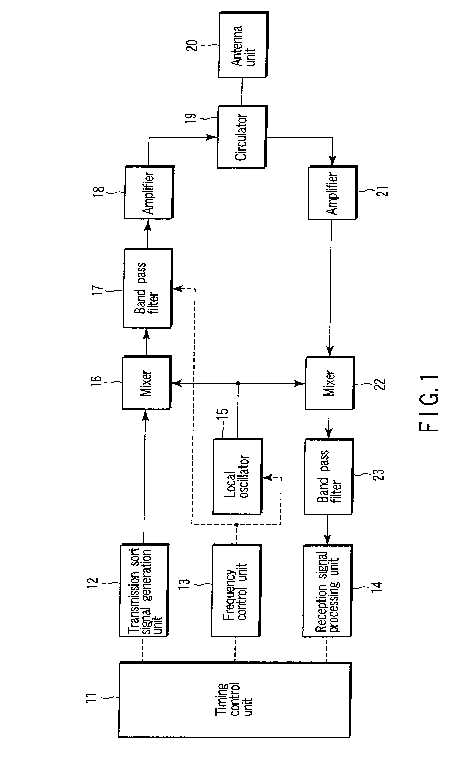
[0019]FIG. 1 is a block diagram showing an example of a configuration of a radar device regarding one embodiment of the invention. In FIG. 1, a timing control unit 11 controls processing of the whole of the device, and mainly controls the processing timings of a transmission sort signal generation unit 12, a frequency control unit 13 and a reception signal processing unit 14.

[0020]The generation unit 12 generates a transmission sort signal of a preset RPF, pulse width and modulation method in accordance with an instruction from the timing control unit 11. The frequency control unit 13 controls an oscillation frequency from a local oscillator 15 and a passing frequency band of a first band pass filter 17, and the reception signal processing unit 14 performs processing to detect a target from a received echo signal.

[0021]By drive control performed by the timing control ...


PUM


Abstract

A radar device includes a generation unit, a transmission unit, and a control unit. The generation unit selectively generates a set of a plurality of transmission signals whose center frequencies are different from one another within an assigned frequency band. The transmission unit emits the transmission signals. The control unit controls the generation unit so as to vary the center frequencies for each emission of the transmission signals.

Description

CROSS REFERENCE TO RELATED APPLICATIONS[0001]This is a Divisional of and claims the benefit of priority under 35 USC § 120 from U.S. Ser. No. 11 / 724,228, filed Mar. 15, 2007, which is a Continuation of PCT Application No. PCT / JP2006 / 320110, filed Oct. 6, 2006, which was published under PCT Article 21(2) in Japanese, which is based upon and claims the benefit of priority from prior Japanese Patent Application No. 2005-295459, filed Oct. 7, 2005, the entire contents of each of which are incorporated herein by reference.BACKGROUND OF THE INVENTION[0002]1. Field of the Invention[0003]The present invention relates to a radar device and a method for adjusting to remove radio wave interference occurring among radar sites.[0004]2. Description of the Related Art[0005]A radar device (hereinafter, referred to as interfered station) sometimes receives a radio wave (hereinafter, referred to as transmission signal) emitted from other adjacent radar devices (hereinafter, referred to as interfering...

Claims


Application Information

Patent Timeline
Patent Type & Authority Applications(United States)
IPC IPC(8): G01S13/00
CPCG01S7/02G01S13/24G01S13/87G01S13/95G01S2013/916Y02A90/10
Inventor KAJIO, HIROSHINANBA, TOSHIO
Owner KK TOSHIBA
Why Eureka
Try Eureka