

Inorganic Scintillator and Process for its Fabrication
a technology of inorganic scintillators and fabrication processes, which is applied in the direction of polycrystalline material growth, crystal growth process, gel state, etc., can solve the problems of low fluorescence intensity output from the scintillator, insufficient energy time resolution, and considerable noise generation of siosub>5/sub>, so as to reduce the detection precision of charged particles, the effect of low energy time resolution and low fluorescence intensity outpu
- Summary
- Abstract
- Description
- Claims
- Application Information
AI Technical Summary
Benefits of technology
Problems solved by technology
Method used
Image

Examples
example 1
[0077] In an Ir crucible having the same shape shown in FIG. 3 with a diameter of 50 mm, a height of 50 mm and a thickness of 1.5 mm there were loaded 316.84 g of gadolinium oxide (Gd2O3, 99.99 wt % purity), 87.06 g of lutetium oxide (Lu2O3, 99.99 wt % purity), 65.73 g of silicon dioxide (SiO2, 99.99 wt % purity) and 0.38 g of cerium oxide (CeO2, 99.99 wt % purity) as the starting materials, and 470.01 g of the mixture was obtained. The mixture was then heated to melting at 1950° C. or higher in a high-frequency induction heating furnace to obtain a melt (chemical composition of melt: Ce0.002Lu0.4Gd1.598SiO5) (melting step).
[0078] Next, the end of the lifting rod to which the seed crystal was anchored was placed in the melt for crystal growth. The seed crystal used was a cut-out single crystal composed of a metal oxide containing Ce0.002Lu0.4Gd1.598SiO5, obtained by an ordinary crystal growth method. After growth of the single crystal and before its cutting (trimming), the crystal ...
example 2
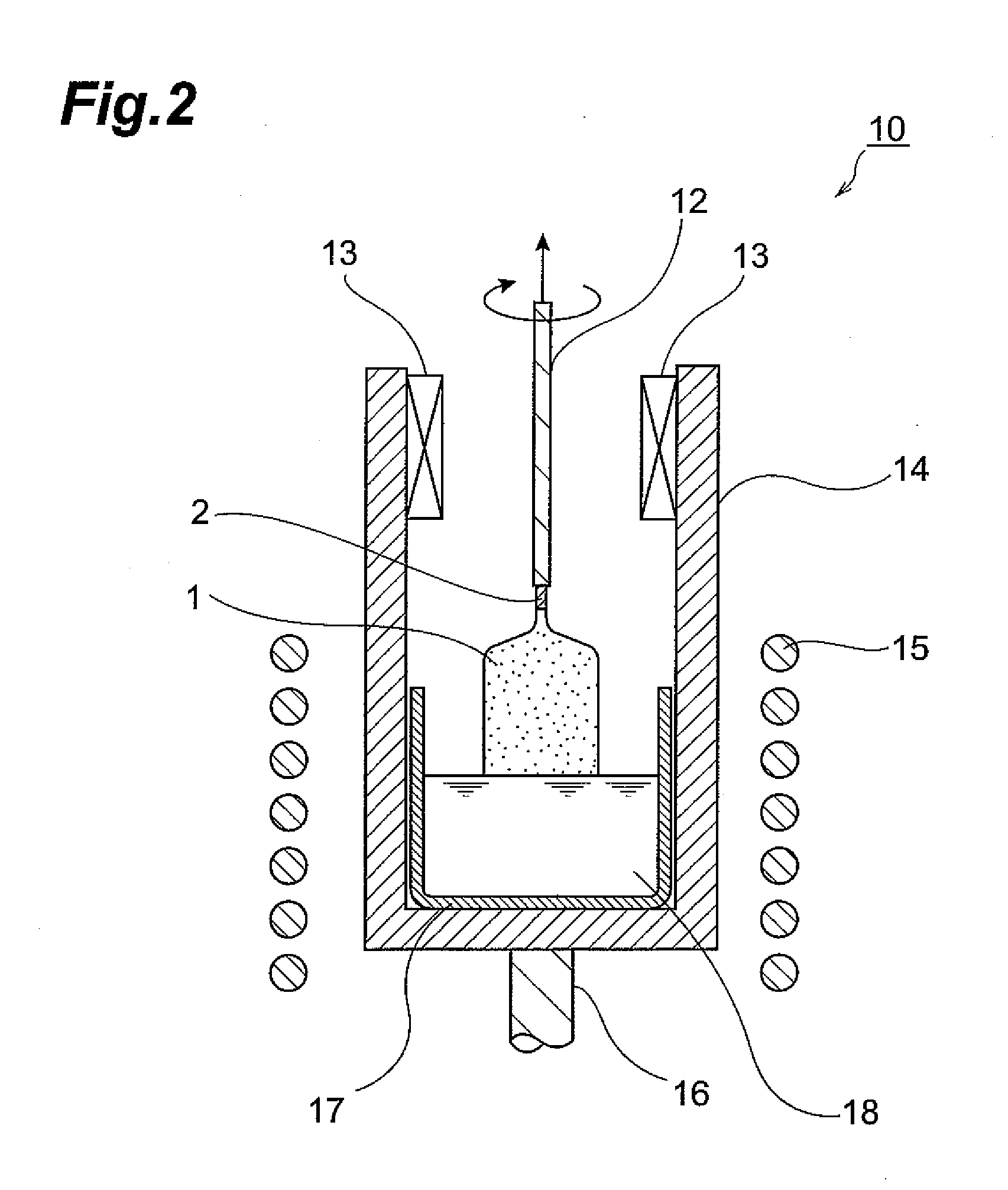
[0085] In an Ir crucible having the same shape shown in FIG. 2 with a diameter of 50 mm, a height of 50 mm and a thickness of 1.5 mm there were loaded 262.67 g of gadolinium oxide (Gd2O3, 99.99 wt % purity), 124.02 g of lutetium oxide (Lu2O3, 99.99 wt % purity), 62.42 g of silicon dioxide (SiO2, 99.99 wt % purity) and 0.89 g of cerium oxide (CeO2, 99.99 wt % purity) as the starting materials, and 450.00 g of the mixture was obtained. The mixture was then heated to melting at 1950° C. or higher in a high-frequency induction heating furnace to obtain a melt (chemical composition of melt: Ce0.005Lu0.6Gd1.395SiO5) (melting step).
[0086] Next, the end of the lifting rod to which the seed crystal was anchored was placed in the melt for crystal growth. The seed crystal used was a cut-out single crystal composed of a metal oxide containing Ce0.005Lu0.6Gd1.395SiO5, obtained by an ordinary crystal growth method. After growth of the single crystal and before its cutting (trimming), the crystal...
example 3
[0092] In an Ir crucible having the same shape shown in FIG. 2 with a diameter of 50 mm, a height of 50 mm and a thickness of 1.5 mm there were loaded 273.54 g of gadolinium oxide (Gd2O3, 99.99 wt % purity), 86.10 g of lutetium oxide (Lu2O3, 99.99 wt % purity), 24.43 g of yttrium oxide (Y2O3, 99.99 wt % purity), 65.00 g of silicon dioxide (SiO2, 99.99 wt % purity) and 0.93 g of cerium oxide (CeO2, 99.99 wt % purity) as the starting materials, and 450.00 g of the mixture was obtained. The mixture was then heated to melting at 1950° C. or higher in a high-frequency induction heating furnace to obtain a melt (chemical composition of melt: Ce0.005Y0.2Lu0.4Gd1.395SiO5) (melting step).
[0093] Next, the end of the lifting rod to which the seed crystal was anchored was placed in the melt for crystal growth. The seed crystal used was a cut-out single crystal composed of a metal oxide containing Ce0.005Y0.2Lu0.4Gd1.395SiO5, obtained by an ordinary crystal growth method. After growth of the si...
PUM
| Property | Measurement | Unit |
|---|---|---|
| natural abundance ratio | aaaaa | aaaaa |
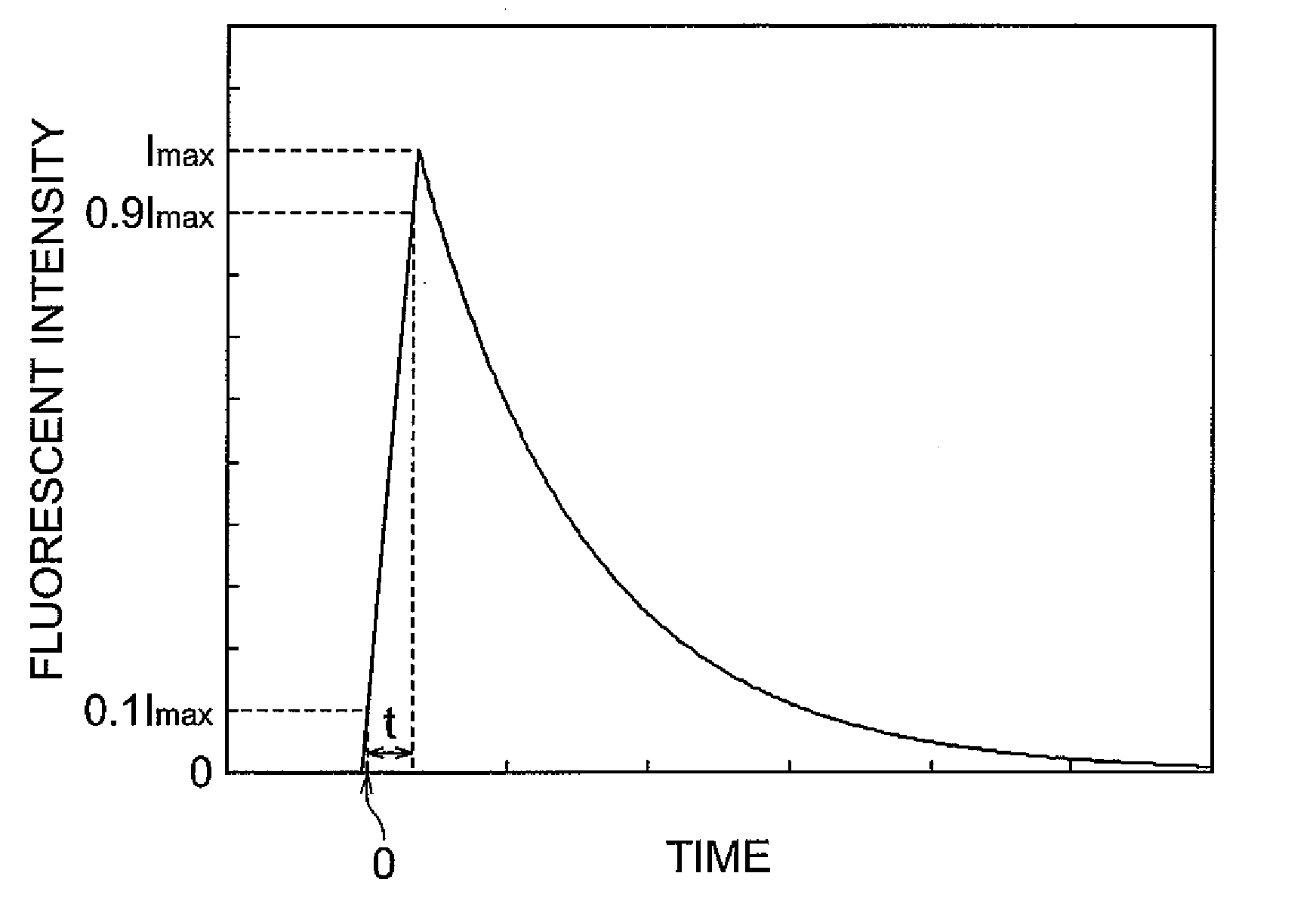
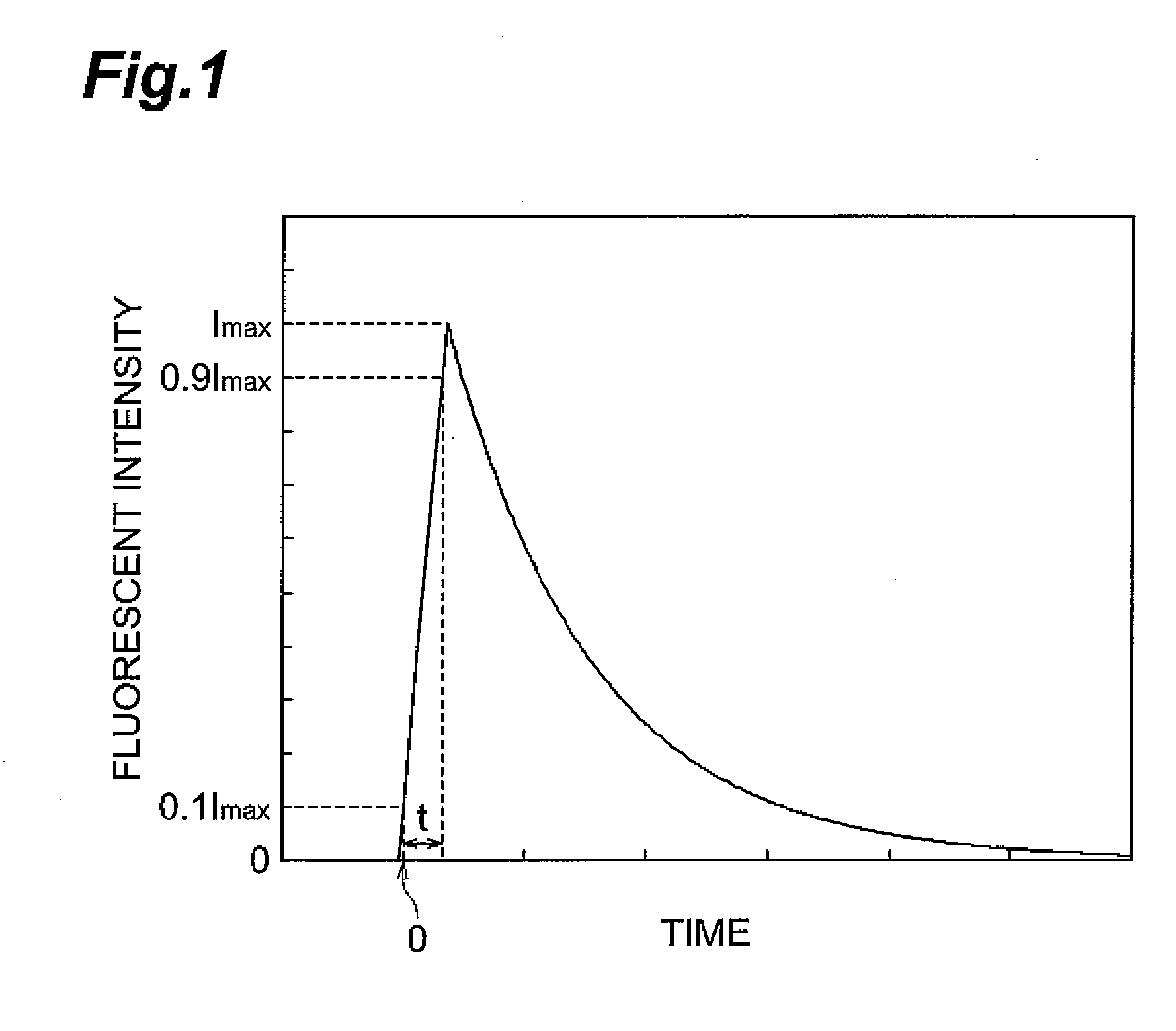
| fluorescent rise time | aaaaa | aaaaa |
| time | aaaaa | aaaaa |
Abstract
Description
Claims
Application Information