

Radar device and method for adjusting among radar sites
- Summary
- Abstract
- Description
- Claims
- Application Information
AI Technical Summary
Benefits of technology
Problems solved by technology
Method used
Image

Examples
Embodiment Construction
[0019] Hereinafter, an embodiment of the present invention will be described in detail with reference to the drawings.
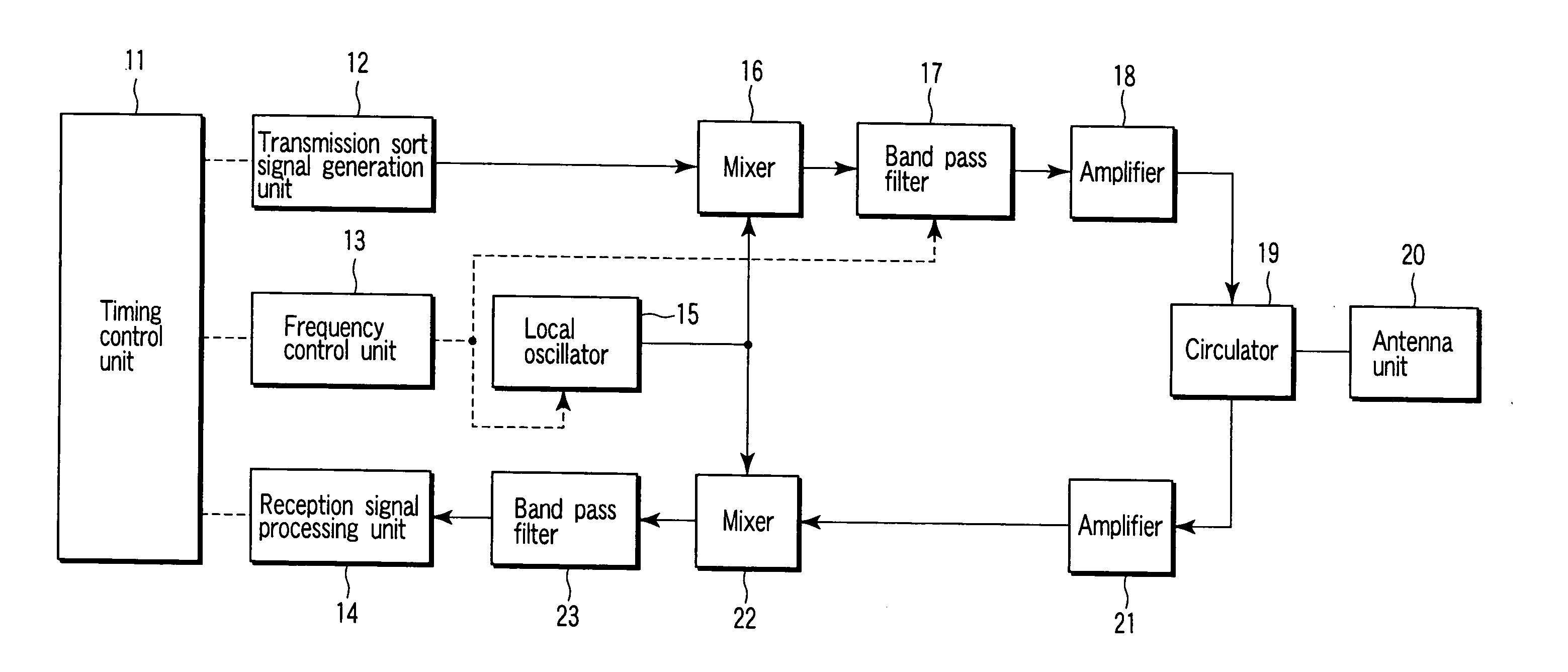
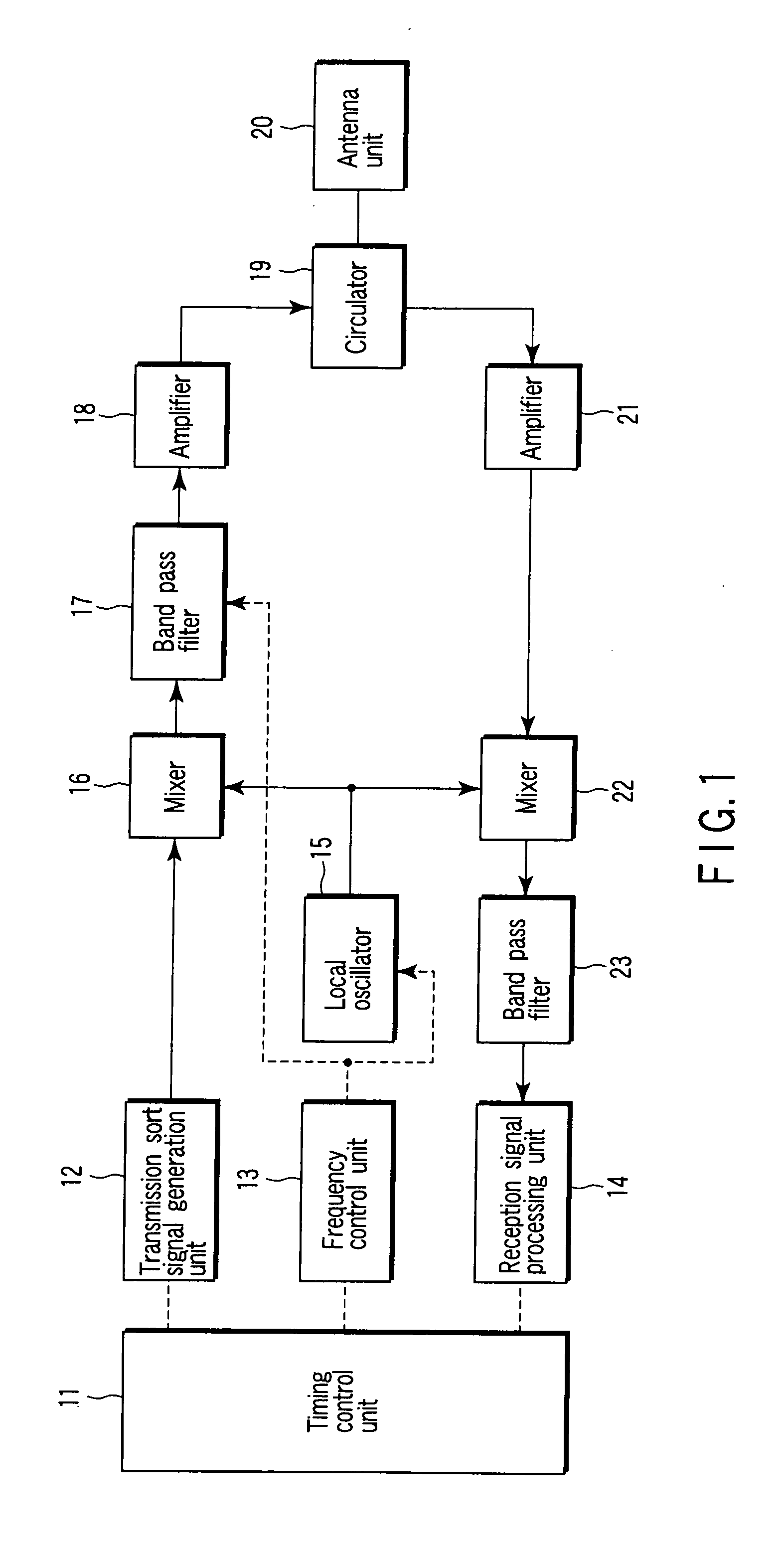
[0020]FIG. 1 is a block diagram showing an example of a configuration of a radar device regarding one embodiment of the invention. In FIG. 1, a timing control unit 11 controls processing of the whole of the device, and mainly controls the processing timings of a transmission sort signal generation unit 12, a frequency control unit 13 and a reception signal processing unit 14.
[0021] The generation unit 12 generates a transmission sort signal of a preset RPF, pulse width and modulation method in accordance with an instruction from the timing control unit 11. The frequency control unit 13 controls an oscillation frequency from a local oscillator 15 and a passing frequency band of a first band pass filter 17, and the reception signal processing unit 14 performs processing to detect a target from a received echo signal.
[0022] By drive control performed by the timing co...
PUM
 Abstract
Description
Claims
Application Information