
Method to ensure temporal synchronization and reduce complexity in the detection of temporal watermarks

a technology of temporal watermarks and synchronization, applied in the field of watermarks, can solve problems such as lens distortion in video cameras, distortion of video cameras, and unintentional distortion during recording processes

Inactive Publication Date: 2008-11-20
SONY ELECTRONICS INC +1
View PDF4 Cites 11 Cited by
  • Summary
  • Abstract
  • Description
  • Claims
  • Application Information

AI Technical Summary

Benefits of technology

[0023]In accordance with one or more aspects of the invention, a method and / or apparatus is capable of detecting a watermark among a plurality of reproduced frames of data, the reproduced frames of data having been derived from respective original frames of data includes: adding at least some of the reproduced frames of data together on a data point-by-data point basis to obtain an aggregate frame of data points; selecting peak data points of the aggregate frame of data points; computing correction information from deviations between the positions of the peak data points within the aggregate frame and expected positions of those peak data points; modifying positions of at least some of the data of at least some of the reproduced frames of data using the correction information such that those reproduced frames of data more closely coincide with respective ones of the original frames of data; and detecting the watermark from among the modified reproduced frames of data.

Problems solved by technology

A pirate may intentionally distort the embedded watermark as discussed above or the distortion may unintentionally occur during the recording process at a theater.
For example, if the pirated copy was recorded, using a video camera, several factors can cause distortion including (i) shaking of the video camera (especially if it is handheld); (ii) misalignment of the video camera with the projected movie (e.g., when the video camera is on a tripod); (iii) lens distortion in the video camera (intentional and / or non-intentional); and (iv) projection screen abnormalities (e.g., curvature).
Further, inadvertent distortion of the embedded watermark may occur during the normal processing of the content data (containing an embedded watermark) in a computer system or consumer device.
For example, the content data (and embedded watermark) of a DVD may be inadvertently distorted while undergoing a formatting process, e.g., that converts the content data from the European PAL TV system to the US NTSC TV system, or vice versa.
Indeed, such processing may inadvertently resize, rotate, and / or translate the content data and, by extension, the embedded watermark, rendering the embedded watermark difficult to detect.
Such editing may also create temporal distortions in movie frames, and may require frame rate conversion or frame compression that distorts or destroys watermark information.
One drawback of such a system is that it requires complex mathematics and a particularly structured embedded watermark pattern and detector.
This system cannot be used with pre-existing watermarking systems.
A disadvantage of such a system is that the design of the embedded watermark must be spatially periodic, which does not always occur in an arbitrary watermarking system.
This system is disadvantageous, however, since the templates tend to be fragile and easily attacked.
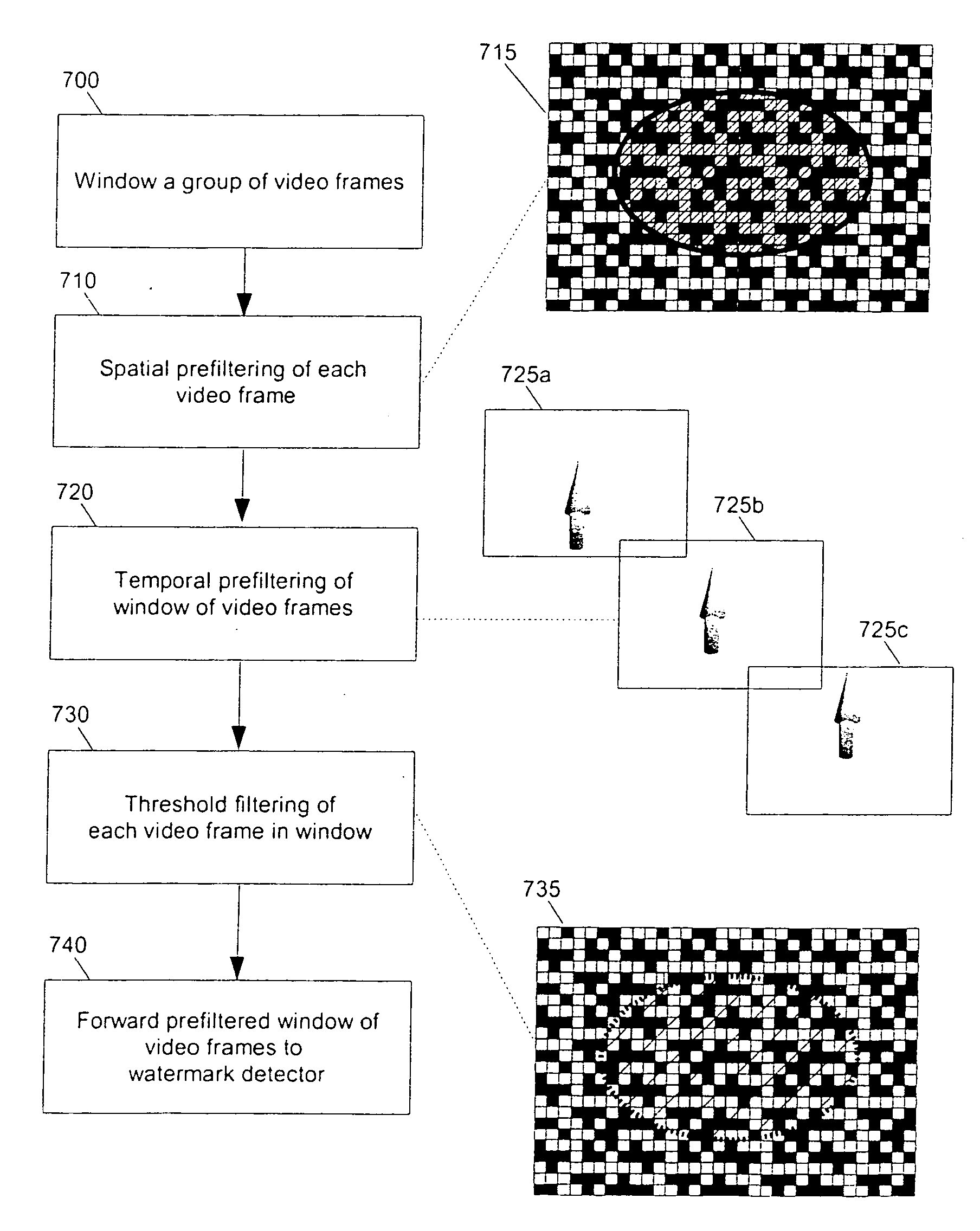
However, this process is rendered more complex if it is not known whether the sequence of watermark patterns and the sequence of coefficients are synchronized.
If, in addition, though, the frame rate of the video has been changed, then the temporal correlation will not work at all.
Nor will the process for determining the offset shift via the combination of N frames for each input frames typically be effective.

Method used


Image

  • Method to ensure temporal synchronization and reduce complexity in the detection of temporal watermarks
  • Method to ensure temporal synchronization and reduce complexity in the detection of temporal watermarks
  • Method to ensure temporal synchronization and reduce complexity in the detection of temporal watermarks

Examples


Embodiment Construction

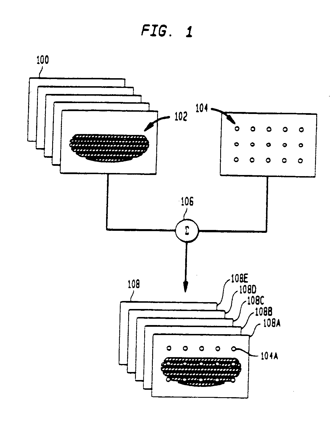
[0055]Referring now to the drawings wherein like numerals indicate like elements, there is shown in FIG. 1 a conceptual block diagram illustrating the use of marker data points in accordance with one or more aspects of the present invention.

[0056]An “original movie” to be shown in a theater includes many frames of data. Prior to distribution of the movie to a particular theater, a plurality of frames of data 100 containing content data 102 are preferably modified to include a number of marker data points 104, preferably arranged in a grid. In particular, the pattern of marker data points 104 are preferably embedded into at least some of the frames of data 100, for example, by way of a summing unit 106. The output of the summing unit 106 is a plurality of frames of data 108, each containing the pattern of marker data points 104 as well as the content data 102. The frames of data 108 may represent substantially all of the frames of data of the movie or may be a subset of such frames o...


PUM


Abstract

A method and / or apparatus for embedding and detecting a watermark among a plurality of frames of data is disclosed, where the watermark is correlated with a plurality of noise blocks, and the noise blocks are summed over a plurality of respective video frames. Each noise block is preferably subjected to a fade function with another noise block over the plurality of respective video frames to make the embedded watermark resistant to changes in data frame rate or other temporal distortions in the frames of data. Detection and recovery of such an embedded watermark and its fade function is also provided.

Description

CROSS-REFERENCE TO RELATED APPLICATIONS[0001]This application is a divisional of U.S. application Ser. No. 10 / 882,055, filed on Jun. 30, 2004, which is a continuation-in-part of U.S. patent application Ser. No. 10 / 383,831, entitled METHOD AND APPARATUS TO DETECT WATERMARK THAT ARE RESISTANT TO ARBITRARY DEFORMATIONS, filed Mar. 7, 2003 (now U.S. Pat. No. 6,782,117), which is a continuation of U.S. patent application Ser. No. 09 / 996,648, now U.S. Pat. No. 6,563,937, entitled METHOD AND APPARATUS TO DETECT WATERMARK THAT ARE RESISTANT TO ARBITRARY DEFORMATIONS, filed Nov. 28, 2001 all of which are assigned to the assignee of the present application and hereby incorporated by reference in their entirety.BACKGROUND OF THE INVENTION[0002]The present invention relates to the detection of one or more watermarks embedded in frames of a moving image and, more particularly, the present invention relates to methods and / or apparatuses for detecting a watermark that are resistant to arbitrary te...

Claims


Application Information

Patent Timeline
Patent Type & Authority Applications(United States)
IPC IPC(8): G06K9/80G06T1/00H04N1/32H04N1/387H04N5/91H04N7/08H04N7/081
CPCG06T1/0064G06T1/0085G06T2201/0051G06T2201/0065H04N1/32149H04N1/32352H04N2201/3233H04N2201/327
Inventor WENDT, PETER D.
Owner SONY ELECTRONICS INC
Learn More