Leaf Clamp for Tubing

a technology of flexible tubing and clamping, which is applied in the direction of diaphragm valves, valve arrangements, other medical devices, etc., can solve the problems of visual obscurity of deflection sets, and achieve the effect of reducing tubing wear and abrasion

a technology of flexible tubing and clamping, which is applied in the direction of diaphragm valves, valve arrangements, other medical devices, etc., can solve the problems of visual obscurity of deflection sets, and achieve the effect of reducing tubing wear and abrasion

US20080290303A1Active Publication Date: 2008-11-27HALKEY ROBERTS CORP

Image

  • Leaf Clamp for Tubing
  • Leaf Clamp for Tubing
  • Leaf Clamp for Tubing

Examples


Embodiment Construction

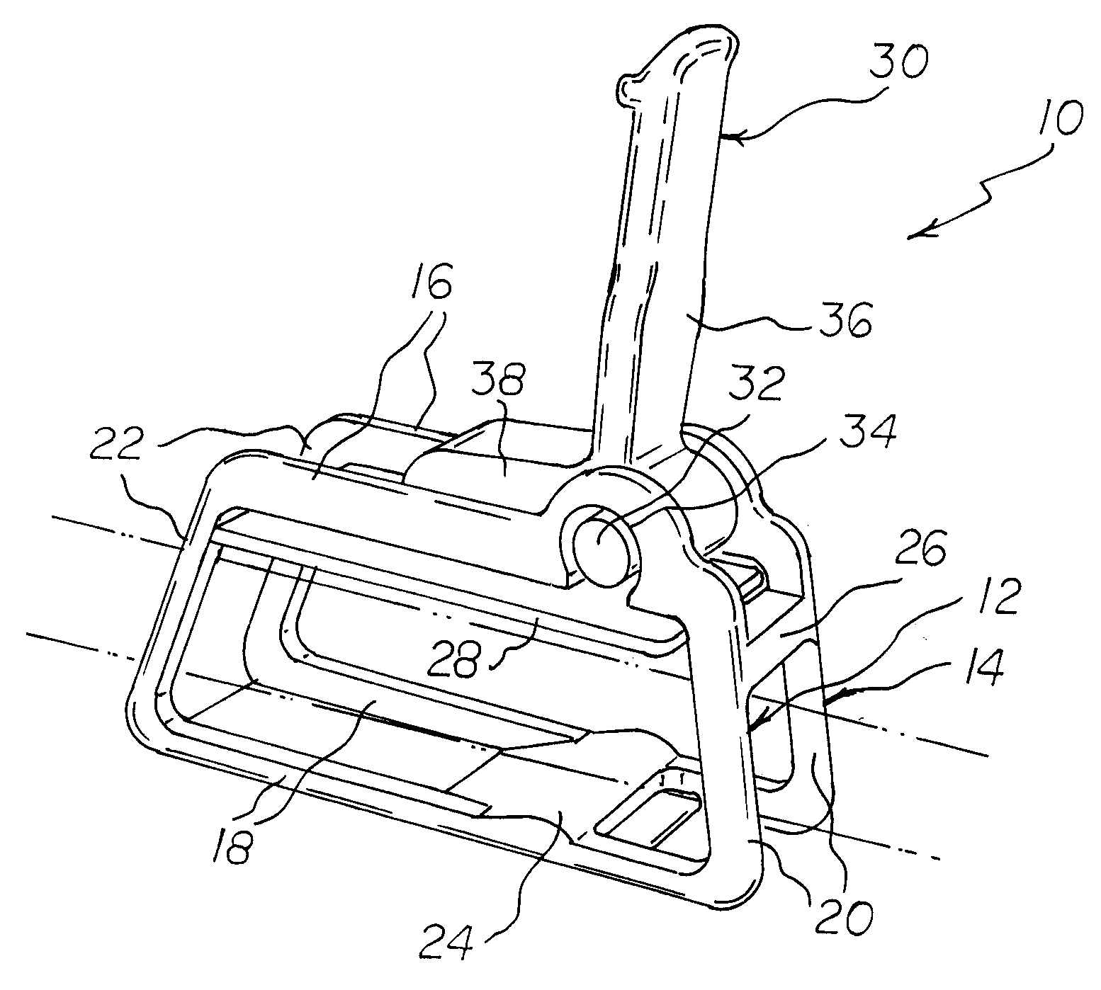
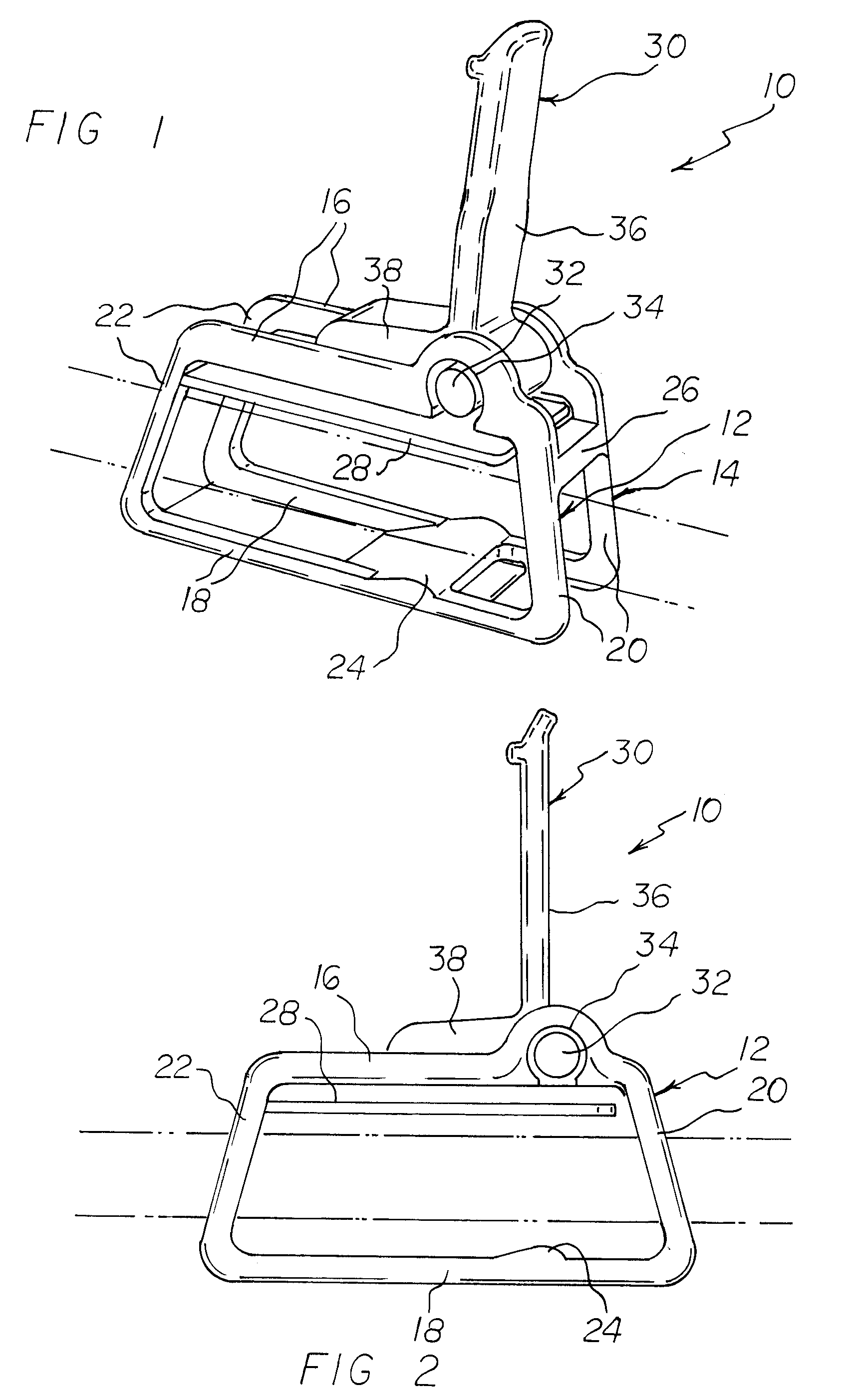
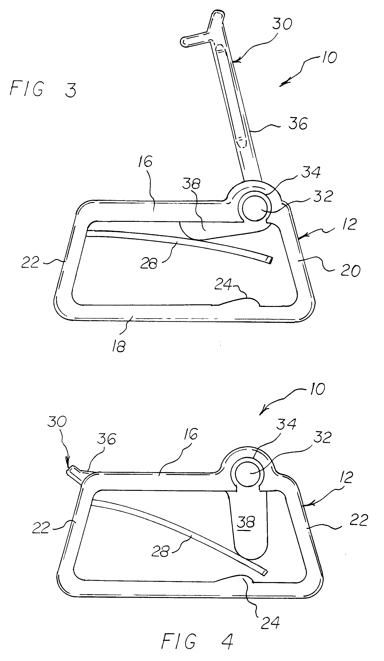
[0031]Referring to FIGS. 1-6, the leaf clamp 10 of the invention comprises a pair of opposing rectilinear frameworks 12 and 14 each comprising an upper frame member 16, a lower frame member 18, a front frame member 20 and a rear frame member 22 forming the rectilinear configuration. The lower frame members 18 are interconnected by a transverse lower member 24 and the front frame members 20 are interconnected by a transverse front member 26. A generally rectangular leaf member 28 interconnects the rear frame members 22 and extends forwardly to a position proximate to the transverse front member 26. The transverse lower member 24, transverse front member 26 and the leaf member 28 secure the rectilinear frameworks 12 and 14 into their spaced-apart opposing relationship with each other.

[0032]The leaf member 28 comprises a generally rectangular configuration that in its relaxed state, extends generally parallel to the upper and lower frame members 16 and 18, but is allowed to pivot downw...


PUM


Abstract

A leaf clamp for installation on tubing to control the flow of fluid therethrough, the leaf clamp comprising opposing rectilinear frameworks between which the tubing is threaded. A flexible leaf interconnects the opposing frameworks and extends generally parallel above the tubing positioned between the rectilinear frameworks. A snap-lever, generally L-shaped, is pivotally connected between the upper portions of the frameworks such that the shorter leg of the L-shaped lever is aligned with and engages the leaf member to urge it downwardly into engagement with the tubing as the longer leg of the L-shaped snap-lever is pivoted from a generally transverse “open” position to a generally parallel “closed” position.

Description

CROSS-REFERENCE TO RELATED APPLICATIONS[0001]This application claims the benefit of provisional patent application 60 / 939,363, filed May 21, 2007, the disclosure of which is hereby incorporated by reference herein.BACKGROUND OF THE INVENTION[0002]1. Field of the Invention[0003]This invention relates to a clamp for hoses or flexible tubing. More particularly, this invention relates to hose clamps commonly used in the medical industry.[0004]2. Description of the Background Art[0005]Presently, there exist many types of clamps for clamping onto a hose or other flexible member to at least partially oculate the hose or to tightly close-off the hose. One particular industry that requires the use of hose clamps is the medical industry wherein hose clamps are used widely as tubing clamps in intravenous administration sets, catheterization kits, and many other medical assemblies.[0006]One of the most common type of tubing clamp in the medical industry comprises a clam-shall design having uppe...

Claims


Application Information

Patent Timeline
27 Nov 2008
Publication
US20080290303A1
IPC
F16K7/06; A61M39/28
CPC
A61M39/284; F16K7/065; F16K7/066
Inventors
MACKAL, GLENN H.