Relay assembly for fog lights

a technology for fog lights and relay assemblies, which is applied in the direction of relays, electric/fluid circuits, transportation and packaging, etc., can solve the problems of cumbersome arrangement and distract the driver's attention, and achieves high reliability, simple construction and design, and easy use.

Inactive Publication Date: 2008-11-27
SPEAR BRIAN
View PDF16 Cites 4 Cited by
  • Summary
  • Abstract
  • Description
  • Claims
  • Application Information

AI Technical Summary

Benefits of technology

[0009]A further object of the present invention is to provide a relay assembly for fog lights that is of simple construction and design and which can be easily employed with highly reliable results.
[0010]Another object of the present invention is to provide a relay assembly for fog lights that does not require any special tools for installation.
[0012]Another object of the present invention is to provide a relay assembly for fog lights that is assembled from common and inexpensive parts.
[0014]A still further object of the present invention is to provide a relay assembly for fog lights that is of unitary construction for easy transportation, installation, and use.

Problems solved by technology

This arrangement is cumbersome for a few reasons.
As can be appreciated, if the driver needs to operate the fog light switch while driving this could distract the attention of the driver and lead to an accident.
Second, if the driver wants to operate the fog lights upon restarting the car the driver must operate the fog light switch.
Third, since the fog lights operate with a beam of light that is difficult to perceive the driver might forget to manually turn the fog light switch on and drive without the benefit of fog lights.
Fourth, some drivers of motor vehicles prefer to have the fog lights illuminated whenever the headlights are illuminated and this forces the driver to always manually select the fog light switch whenever the headlights are automatically illuminated.

Method used


Image

  • Relay assembly for fog lights
  • Relay assembly for fog lights
  • Relay assembly for fog lights

Examples


Embodiment Construction

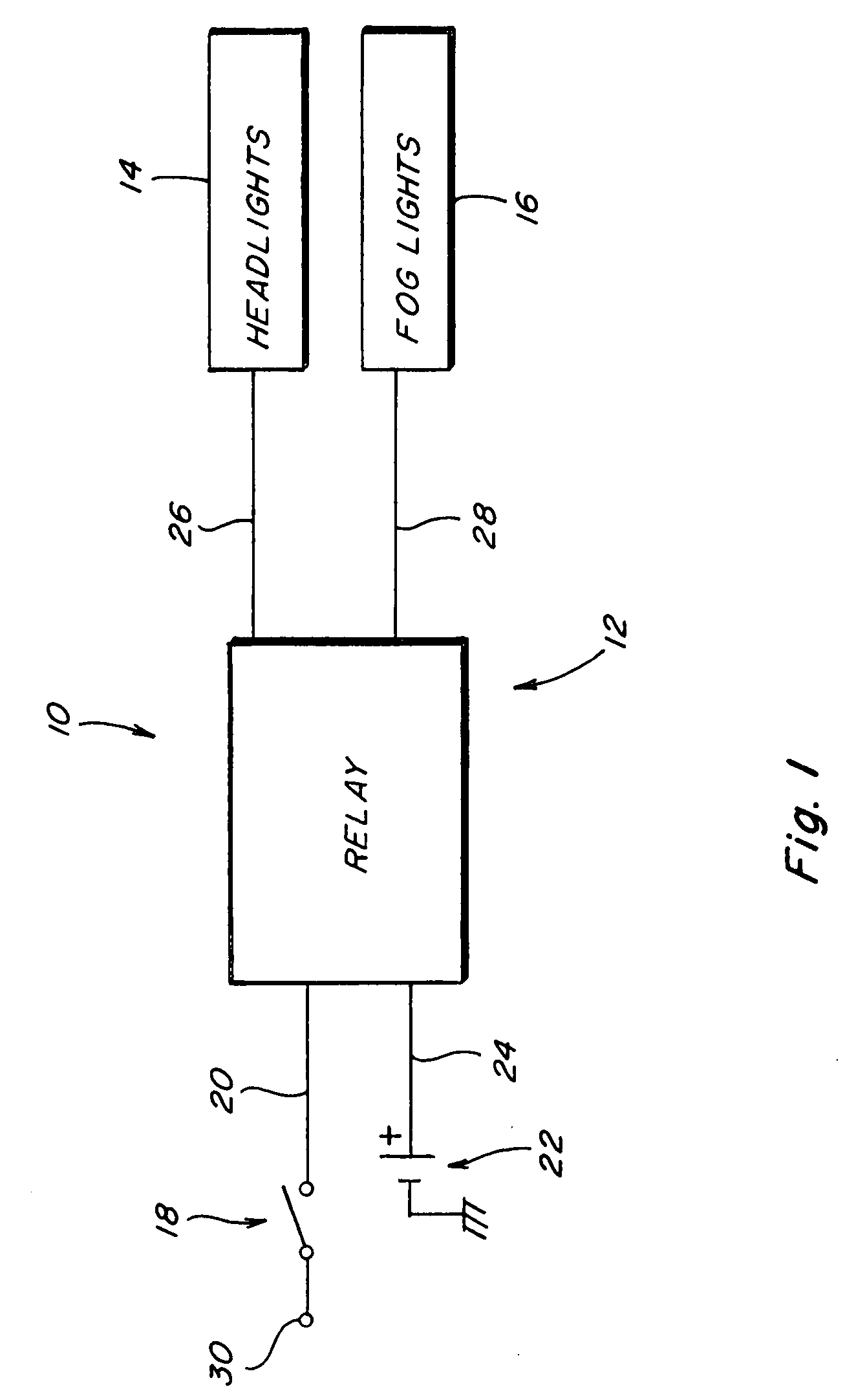
[0024]Referring now to the drawings, wherein like numbers refer to like items, number 10 identifies a preferred embodiment of a relay assembly for fog lights constructed according to the present invention. With reference now to FIG. 1, the relay assembly 10 is shown connected in a circuit 12 that is used to illuminate headlights 14 and fog lights 16 that are found on an automobile (not shown). The relay assembly 10 is connected to a headlight switch 18 by a wire 20. The relay assembly 10 is also connected to a battery 22 via a wire 24. The headlights 14 are connected to the relay assembly 10 by a connection 26 and the fog lights 16 are also connected to the relay assembly 10 via a connection 28. A junction 30 is connected to a power source such as the battery 22 so that when the switch 18 is closed power is provided to the relay assembly 10.

[0025]In operation, when the switch 18 is operated a voltage is provided to the relay assembly 10 which will in turn provide power to the headli...


PUM


Abstract

A relay assembly for a fog light is disclosed which comprises a relay housing having a first terminal adapted to being connected to a switch for operating another light and operation of the switch for illuminating a fog light.

Description

BACKGROUND OF THE INVENTION[0001]This invention relates to a circuit for controlling the operation of motor vehicle fog lights and more particularly to a relay assembly for controlling the operation of fog lights for an automobile.[0002]Automobiles are manufactured having headlights used to project beams of light during periods of darkness or low light. Such headlights may produce high beams, low beams, and day time driving beams. Automobiles may also be fitted with fog lights that assist with driving in fog conditions. Additionally, fog lights are used to improve visibility at night and during severe weather conditions. Some drivers prefer that fog nights be illuminated whenever the headlights are operated to enhance visibility and safety. Automobiles may use photo detectors connected to the headlights to automatically turn on the headlights when low light or no light is detected. A light switch may be provided on a dashboard of an automobile that may have several different setting...

Claims


Application Information

Patent Timeline
Patent Type & Authority Applications(United States)
IPC IPC(8): B60R16/02
CPCB60Q1/20
Inventor SPEAR, BRIAN
Owner SPEAR BRIAN
Why Eureka
Try Eureka