
In-Mold Protective Helmet Having Integrated Ventilation System

Active Publication Date: 2008-12-04
RESOLUTION STRATEGIC DEV
View PDF31 Cites 26 Cited by
  • Summary
  • Abstract
  • Description
  • Claims
  • Application Information

AI Technical Summary

Benefits of technology

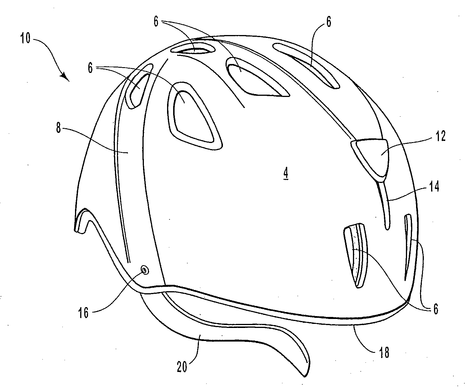
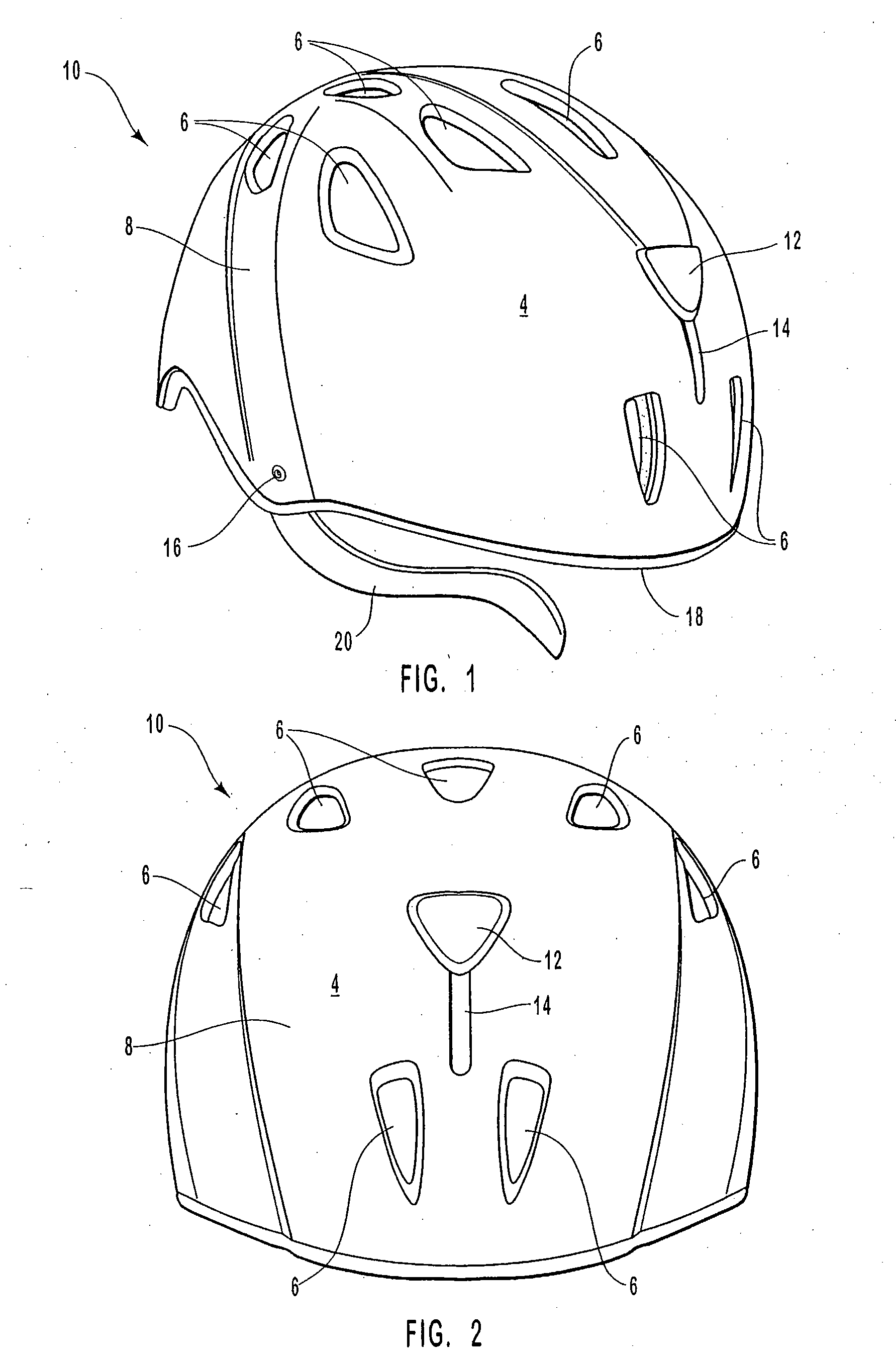
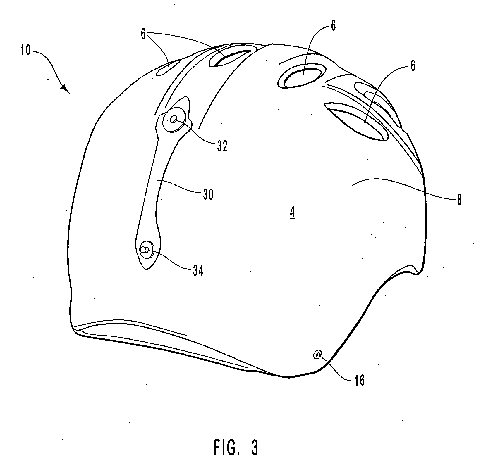
[0019]To achieve the foregoing objects, and in accordance with the invention as embodied and broadly described herein, the preferred embodiment of the present invention, and each of the variations of the preferred embodiment, features a lightweight protective helmet, with an outer shell and an inner liner that is directly molded or bonded to the outer shell thus forming a shell / liner composite, and an improved ventilation system and method for manufacturing the same.

Problems solved by technology

Despite their significant improvements and advancements, as mentioned above, protective helmets continue to suffer from inadequate and often poor ventilation systems.

Method used


Image

  • In-Mold Protective Helmet Having Integrated Ventilation System
  • In-Mold Protective Helmet Having Integrated Ventilation System
  • In-Mold Protective Helmet Having Integrated Ventilation System

Examples


first embodiment

[0083]FIG. 6 illustrates another configuration of this first embodiment of protective helmet 10, wherein protective helmet 10 has a single large front vent port 6 controlled by actuator 12.

[0084]FIG. 7 illustrates another yet another configuration of this first embodiment of protective helmet 10, in which helmet 10 has a single actuator 12 that controls the flow of ambient air into two front vent ports 6.

[0085]FIG. 8 illustrates still another configuration of this first embodiment of protective helmet 10, in which helmet 10 has two separate and independent front ventilation systems. The ventilation systems each comprise first and second vent ports, and first and second respective or corresponding actuators.

[0086]FIG. 9 illustrates protective helmet 10 of the present invention having aggressive raised intake busters 70.

[0087]FIG. 10 illustrates a second, alternative embodiment of the protective helmet of the present invention. Protective helmet 10 comprises outer shell 4 joined (mold...

third embodiment

[0095]FIG. 12-B shows a variation on this third embodiment to protective helmet 10. Specifically, second shell 62, as described above, may serve as the upper member or plate of vent box 22, such that second shell 62 and lower member 26 define volume of space As vent box 22 is comprised of a lower plate and an upper plate, the inside surface of second shell 62 defines the upper plate of vent box 22, thereby also creating volume of space 28, wherein vent shield 20 may be housed. The displacing of vent shield 20 may be controlled by the wearer, such that any vent ports may be open, partially open, or closed to the flow of ambient air much the same way as described above. Attachment of vent box 22 and second shell 62 may be by any known means.

[0096]FIG. 13 shows yet another variation of this third embodiment of the present invention. Specifically, shell 4 may serve as the lower member or plate of vent box 22 of the ventilation system and the upper member or plate may be comprised of a r...


PUM


Abstract

The present invention provides a lightweight protective helmet having an improved ventilation system therein. The protective helmet comprises an outer shell and an inner liner that are joined together to form a shell / liner composite. The ventilation system interacts with one or more ventilation ports in the protective helmet to control the flow of ambient air in and out of the interior of the protective helmet. The ventilation system may be integrated or encased within the shell / liner composite, or it may be adapted to be used on the exterior of the helmet. In addition, the ventilation system may include one of several types of interchangeable insert members to allow active or passive control of ambient air into the interior of the helmet.

Description

RELATED APPLICATIONS[0001]This application is a continuation of U.S. patent application Ser. No. 10 / 447,686, filed May 29, 2003, and entitled, “In-Mold Protective Helmet Having Integrated Ventilation System,” which claims priority to U.S. Provisional Application No. 60 / 383,907, filed May 29, 2002, and entitled, “Protective Helmet Having Improved Integrated Ventilation System,” which is incorporated by reference herein.BACKGROUND[0002]1. Field of the Invention[0003]The present invention relates to protective helmets designed to protect the user from potential impacts to the head during bicycling, skiing, snowboarding, and other sporting adventures. Specifically, the present invention relates to a protective helmet providing improved ambient airflow throughout the interior of the helmet using a unique ported and adjustable fluid airflow system.[0004]2. Background of the Invention[0005]Athletes and outdoor enthusiasts alike have long recognized the importance of wearing protective head...

Claims


Application Information

Patent Timeline
IPC IPC(8): A42B3/00A42C5/04A42B3/28
CPCA42B3/283A42B3/12
Inventor MUSKOVITZ, DAVID T.
Owner RESOLUTION STRATEGIC DEV
Learn More