Energy Saving Seal With Rocking Dust Lip

Active Publication Date: 2015-08-06
FREUDENBERG NOK GEN PARTNERSHIP
View PDF12 Cites 7 Cited by
  • Summary
  • Abstract
  • Description
  • Claims
  • Application Information

AI Technical Summary

Benefits of technology

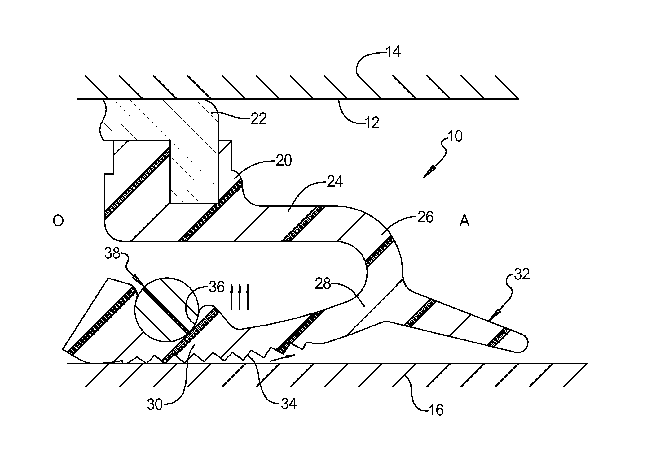
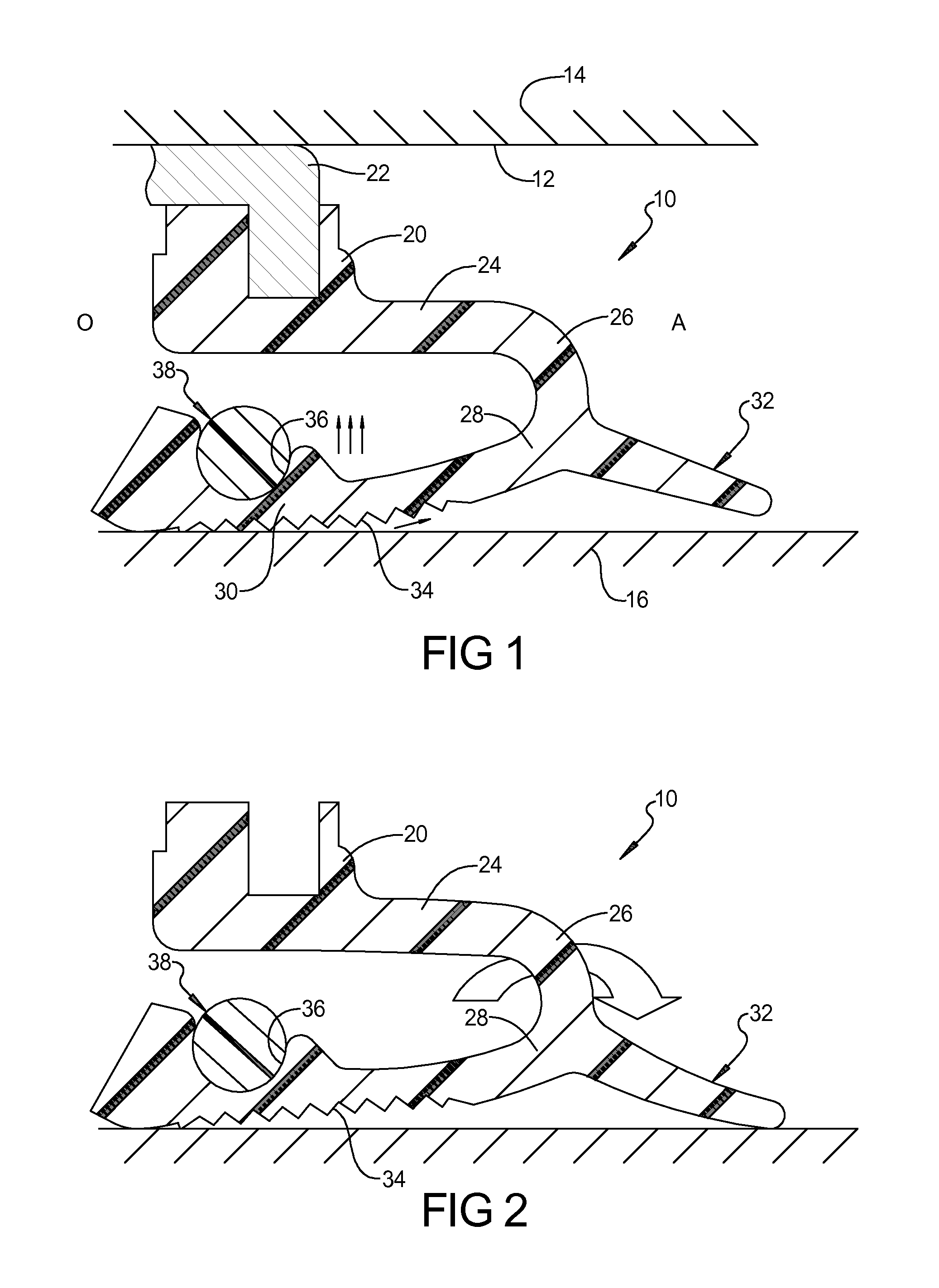
[0020]Under operating conditions with negative pressure on the oil side O, the negative pressure tends to cause the lay down sealing lip 30 to lift off of the shaft 16, there is a counterbalance force that is applied to the axial leg 24 which maintains the lay down sealing lip 30 in contac

Problems solved by technology

However, in certain forced induction engines such as turbocharged and supercharged engines, the crankcase pressure becomes negative and exceeds the capacity of the lay down

Method used


Image

  • Energy Saving Seal With Rocking Dust Lip
  • Energy Saving Seal With Rocking Dust Lip
  • Energy Saving Seal With Rocking Dust Lip

Examples


Embodiment Construction

[0012]Example embodiments will now be described more fully with reference to the accompanying drawings.

[0013]Example embodiments are provided so that this disclosure will be thorough, and will fully convey the scope to those who are skilled in the art. Numerous specific details are set forth such as examples of specific components, devices, and methods, to provide a thorough understanding of embodiments of the present disclosure. It will be apparent to those skilled in the art that specific details need not be employed, that example embodiments may be embodied in many different forms and that neither should be construed to limit the scope of the disclosure. In some example embodiments, well-known processes, well-known device structures, and well-known technologies are not described in detail.

[0014]The terminology used herein is for the purpose of describing particular example embodiments only and is not intended to be limiting. As used herein, the singular forms “a,”“an,” and “the” ...


PUM


Abstract

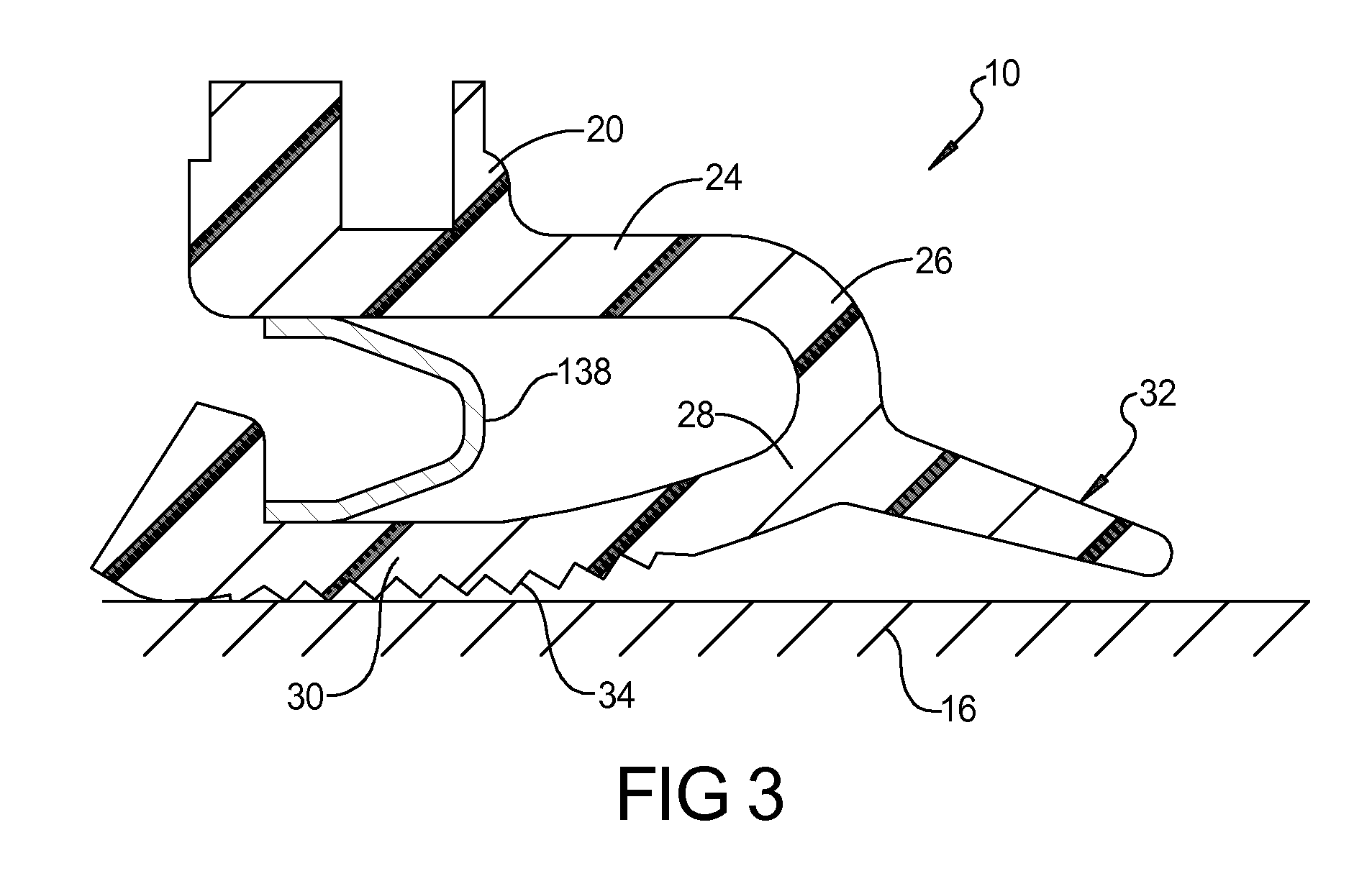
A seal includes an annular mounting portion having an axial leg extending axially from the annular mounting portion toward the air side. A radial leg portion extends radially inward from an end of the axial leg. A lay down sealing lip extends radially inward and axially toward the oil side from an end of the radial leg portion. A dust lip extends from the end of the radial leg portion in a direction opposite the lay down sealing lip. When the oil side is under negative pressure and when the lay down sealing lip begins to lift radially off the shaft, there is a counterbalance force applied to the axial leg that is designed to be flexible enough that the oil side vacuum “rocks” the seal bringing the dust lip into contact with the shaft and blocking airflow.

Description

FIELD[0001]The present disclosure relates to a dynamic shaft seal and more particularly to an energy-saving seal with rocking dust lip feature.BACKGROUND[0002]This section provides background information related to the present disclosure which is not necessarily prior art.[0003]Currently, lay down lip seals offering low power consumption due to low friction are recommended for use in engines with relatively low levels of crankcase pressure. The seal's radial force is sufficient to keep the lip in contact with a shaft for desired sealing performance yet is low enough to cause minimum friction. However, in certain forced induction engines such as turbocharged and supercharged engines, the crankcase pressure becomes negative and exceeds the capacity of the lay down lip seal to remain in contact with the shaft. This leads to the generation of an air flow from the environment to the crankcase. Interaction of this air flow with the sealing lip, oil and the shaft produces noise / squeal whic...

Claims


Application Information

Patent Timeline
IPC IPC(8): F16J15/32F16J15/16
CPCF16J15/3208F16J15/3236F16J15/164F16J15/3212F16J15/3244F16J15/322F16J15/3232
Inventor BERDICHEVSKY, ALEXANDERSESHADRI, ROHIT
Owner FREUDENBERG NOK GEN PARTNERSHIP
Why Eureka
Try Eureka