Vacuum cleaner and insert part of a vacuum cleaner

A technology for vacuum cleaners and inserts, applied in the directions of vacuum cleaners, cleaning equipment, household appliances, etc., can solve the problems of high cost, laborious processing and assembly, etc., and achieve the effect of enhancing purposeful flow and avoiding eddy currents

Inactive Publication Date: 2011-07-13
BSH BOSCH & SIEMENS HAUSGERAETE GMBH
View PDF10 Cites 0 Cited by
  • Summary
  • Abstract
  • Description
  • Claims
  • Application Information

AI Technical Summary

Problems solved by technology

However, the processing and assembly of such a dustbag basket is relatively labor-intensive and expensive

Method used


Image

  • Vacuum cleaner and insert part of a vacuum cleaner
  • Vacuum cleaner and insert part of a vacuum cleaner
  • Vacuum cleaner and insert part of a vacuum cleaner

Examples


Embodiment Construction

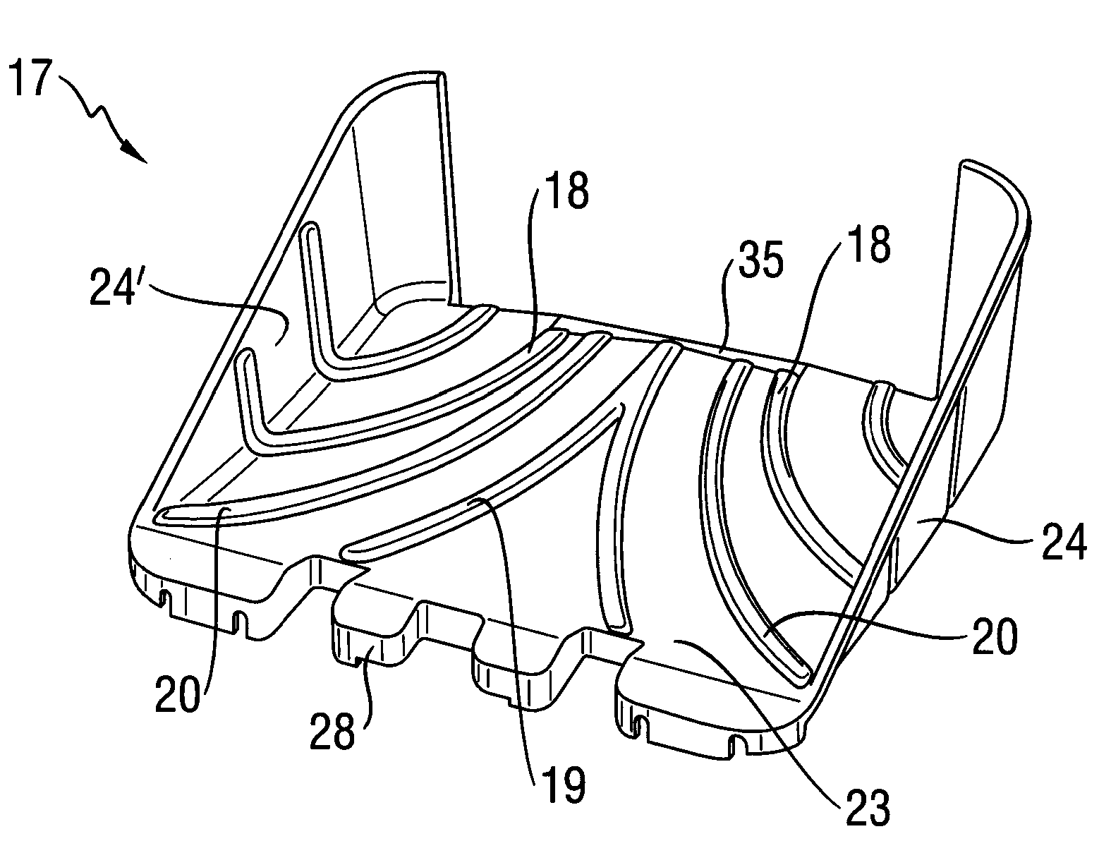
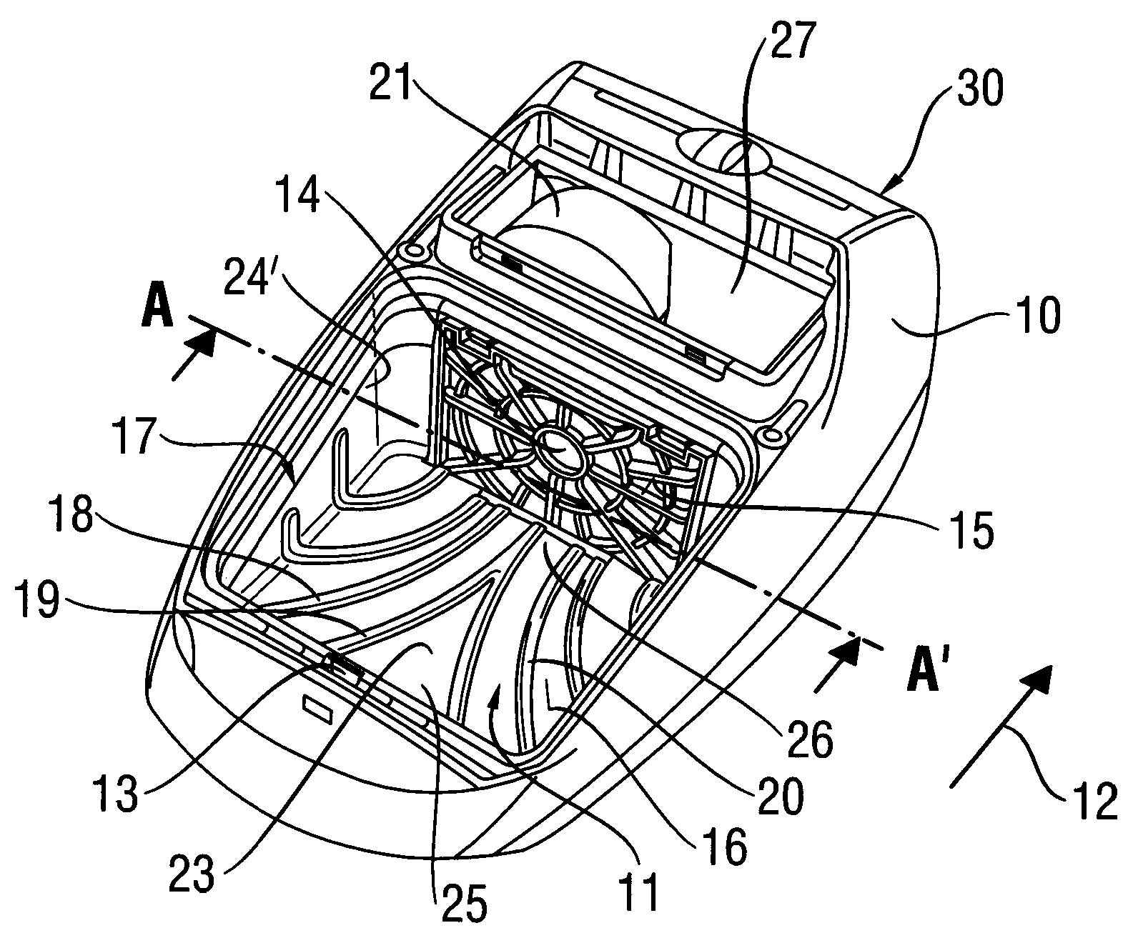
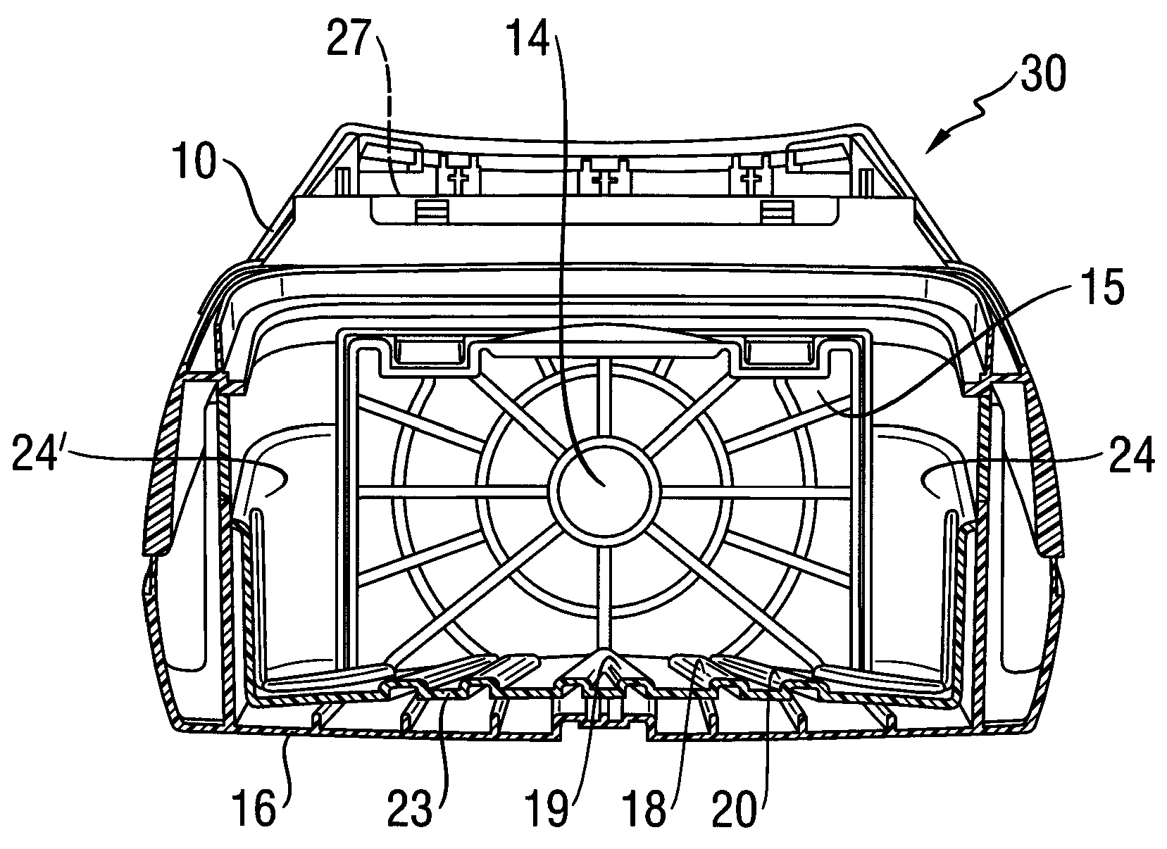
[0029] figure 1 A perspective view of a preferred exemplary embodiment of an insert 17 with ribs 18 , 19 , 20 for a dust chamber 11 of a vacuum cleaner 30 is shown. figure 2 shows the assembled state of the insert 17 and the vacuum cleaner 30, image 3 Shown along the section line A-A' figure 2 cutaway view.

[0030] The vacuum cleaner 30 has a housing 10 with a dust chamber 11 arranged in the housing 10 in which a not shown dust container is arranged. The dust chamber 11 can be opened via a dust chamber cover. exist figure 2 The vacuum cleaner 30 is shown without a dust chamber cover. The blower chamber 27 is adjacent to the dust chamber 11, and the blower 21 is provided in the blower chamber. Air is sucked in from the dust chamber 11 by the blower 21 through the air outlet 14 . The sucked-in air flows into the dust chamber 11 via an air inlet 13 via a connection (not shown). The dust chamber 11 is thus loaded with a negative pressure and the clean air flow 22 (see...


PUM


Abstract

The invention relates to a vacuum cleaner comprising a housing (10) and a dust chamber (11) disposed in the housing (10) for accommodating a dust collection container, wherein the housing (10) comprises an air inlet opening (13) and an air outlet opening (14) for an air stream (22), wherein a first border wall (15) of the dust chamber (11) is associated with the air outlet opening (14). It is proposed that an insert part (17) with flow guide ribs (18, 19, 20) is disposed at at least one of the other border walls (16) of the dust chamber (11), said ribs guiding the incoming air stream (22) in a targeted manner from the air inlet opening (13) to the air outlet opening (14). The invention further relates to vacuum cleaners comprising base ribs (36, 37) that are designed similarly to the flow guide ribs (18, 19, 20) of the insert part (17).

Description

technical field [0001] The invention relates to a vacuum cleaner with a housing and a dust chamber arranged in the housing for accommodating a dust collection container, wherein the housing has an air inlet and an air outlet for an air flow, wherein a first delimiting wall of the dust chamber is attached to the air outlet . Background technique [0002] Vacuum cleaners are known with a housing which, in particular at the bottom region, at least partially has longitudinal, transverse and / or cross-shaped air guide ribs, which can be used for reinforcement. However, such air guide ribs can also have other functions, for example the wake behavior of the dust bag described in DE 198 01 762 A1. In this case, the dust bag can rest directly on the air guide ribs or be fixed in an insertable auxiliary device. [0003] For example, a filter box is known from DE 73 72 289 U1 with a surrounding clip, which on the one hand fixes the dust container in the operating position and on the o...

Claims


Application Information

Patent Timeline
Patent Type & Authority Applications(China)
IPC IPC(8): A47L9/00
CPCA47L9/00
Inventor S・哈姆J・克莱姆A・米夏尔斯T・泽特
Owner BSH BOSCH & SIEMENS HAUSGERAETE GMBH
Why Eureka
Try Eureka