[0013]It is an object of the present invention to further enhance and improve the efficiency and installation cost functionality of prior art direct expansion geothermal heat exchange designs. This is accomplished by means of providing an insulated, sub-surface, smaller interior
diameter, refrigerant transport line, or tube, designed to transport liquid / fluid refrigerant in a sub-surface environment, which is operatively connected to at least one, larger interior
diameter, and preferably two combined larger interior
diameter, un-insulated, sub-surface refrigerant vapor /
fluid transport lines, or tubes, which vapor lines are in direct
thermal contact with sub-surface, heat-conductive, elements.
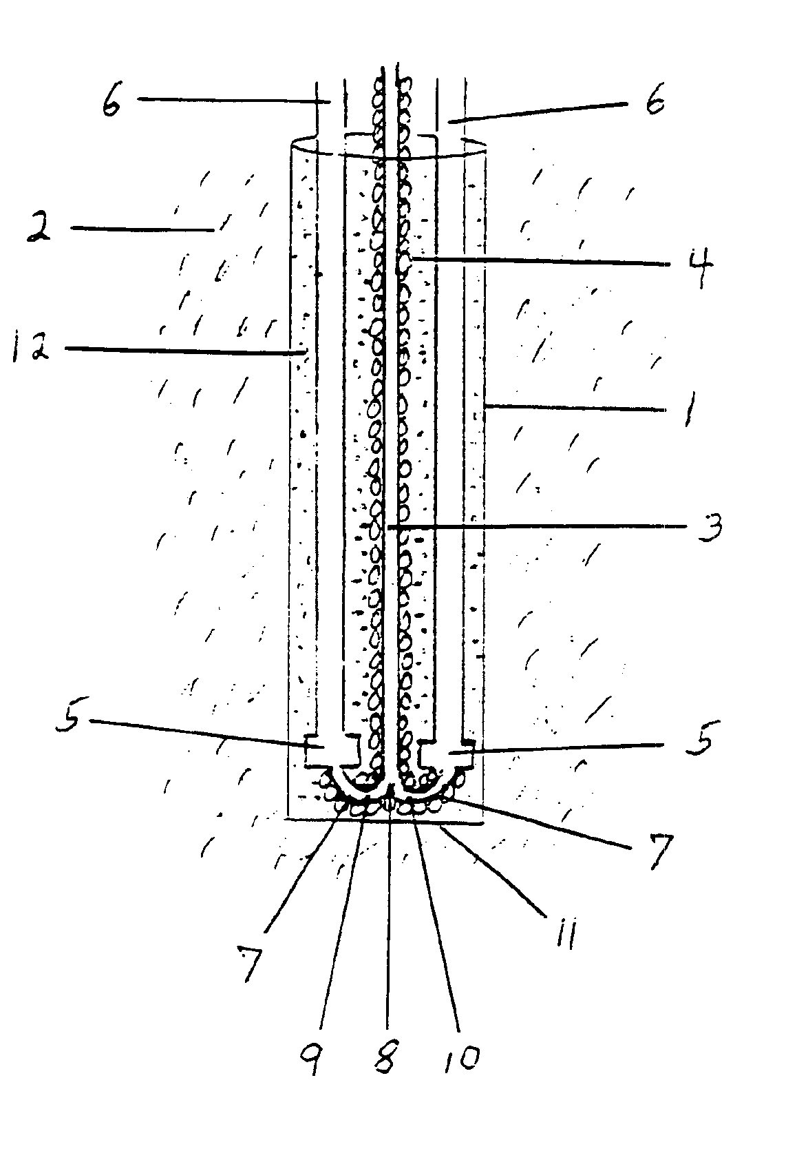
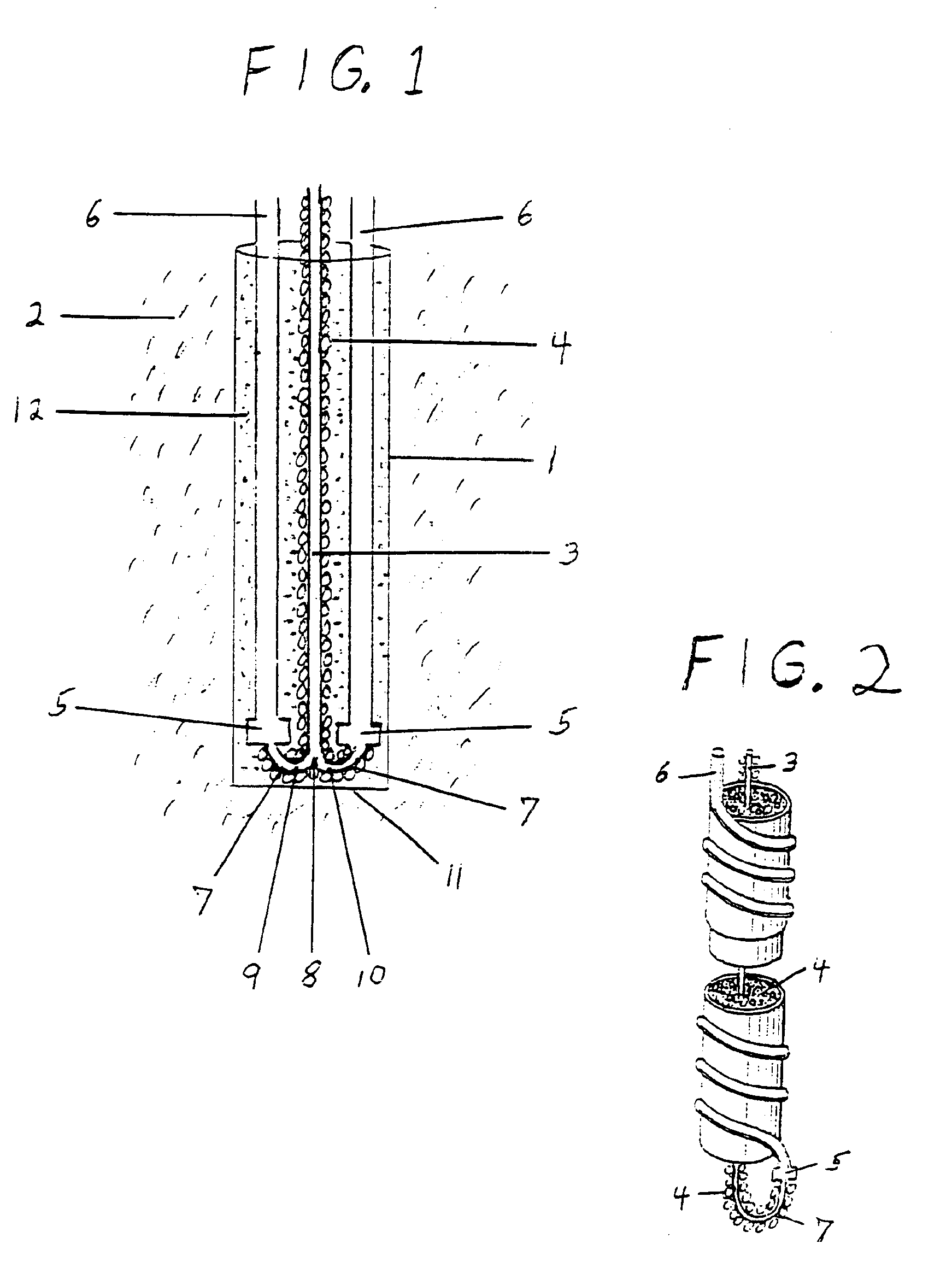
[0015]To accomplish these preferable objectives, the present invention includes fully insulated, smaller interior diameter refrigerant
fluid transport line, which insulated fluid
transfer line extends the full depth and / or length of the
geothermal fluid transfer unit, generally placed within a borehole, which line is primarily designed to transport a refrigerant liquid / fluid, and which line is operatively connected to at least one, and preferably two, adjacent, non-insulated, thermally exposed, larger combined interior diameter, refrigerant
fluid transport lines, where the larger combined interior diameter refrigerant transport lines are primarily designed to transport a heat-conductive refrigerant vapor / fluid, and where the larger interior diameter
heat transfer lines are in direct
thermal contact with the sub-surface elements, whether soil and / or rock and / or clay and / or sand and / or water and / or anti-freeze and / or thermal
grout, etc. This method provides ease of installation, reduced installation costs, and more evenly distributes
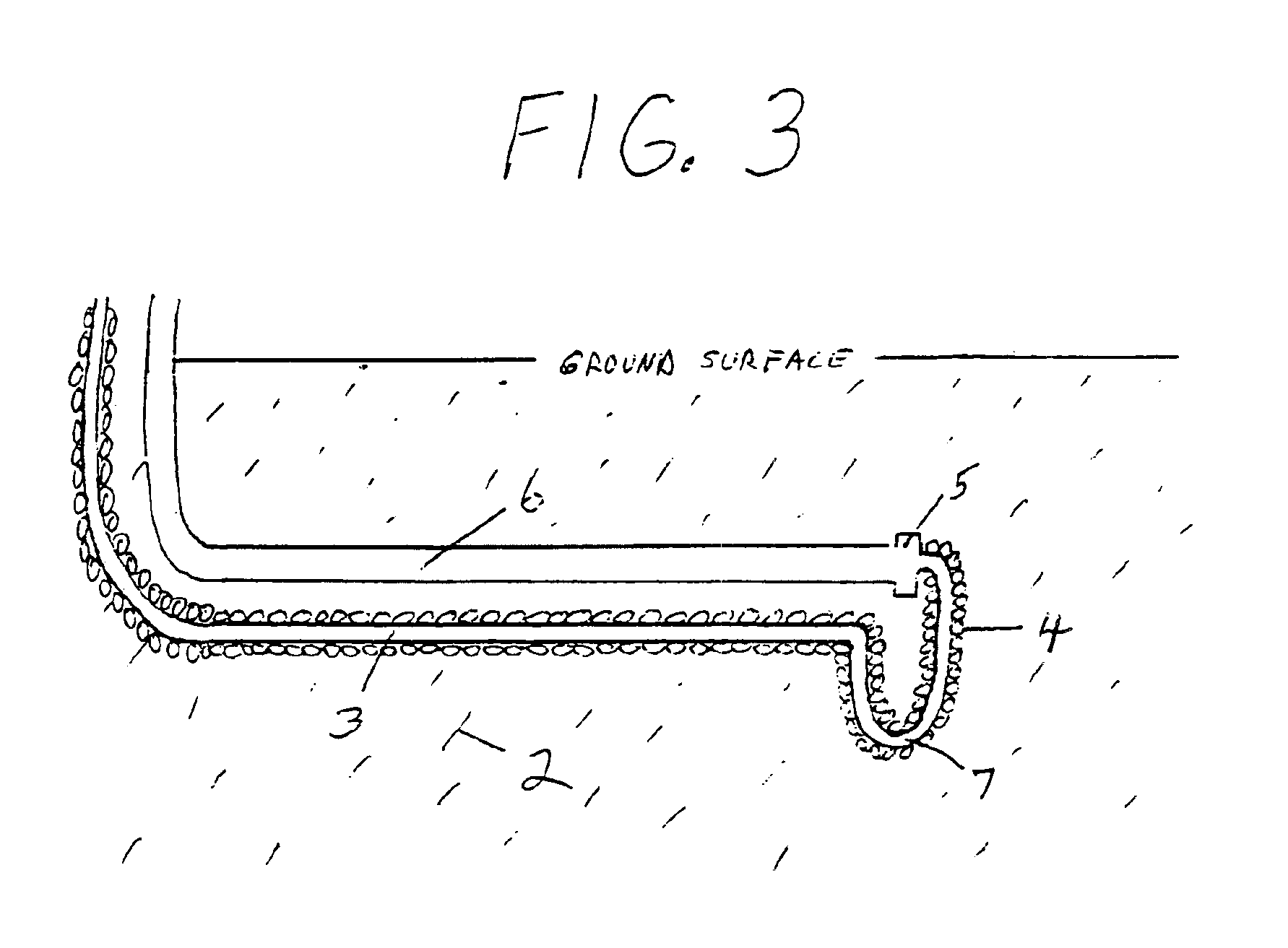
heat transfer, with more heat transfer contact surface area than a typical single heat
transfer line, within either a near surface, or a deep well, direct expansion sub-surface excavation or borehole, all while thermally insulating the smaller interior diameter liquid / fluid refrigerant transport line so as to avoid virtually all potential short-circuiting in-efficiencies, whether operating in the supply or return
modes, in a reverse-cycle system.
[0018]For a direct expansion system, the present invention will additionally facilitate ease of system installation, with the one, and preferably at least two, refrigerant vapor / fluid lines simply being attached to the exterior of the insulation surrounding the central insulated refrigerant liquid / fluid line, typically with each of two respective lines attached on opposite sides of the insulated liquid / fluid line for better heat transfer distribution, with the entire
assembly then being lowered into the borehole. A good method of insulating the smaller interior diameter liquid / fluid refrigerant line is to surround the line with rubatex insulation, or the like, and then to place the rubatex insulated line within a plastic
pipe. The plastic
pipe will enhance insulation properties, will provide a firm support to attach the larger interior diameter vapor / fluid refrigerant transport line, or lines, to, and will help to prevent the rubatex from tearing as the
assembly is lowered into a deep well borehole. In the heating mode, the sub-surface's natural geothermal heat content operates as the
evaporator, with the cold liquid refrigerant flowing from the interior
air handler into the sub-surface surrounding via the smaller interior diameter liquid / fluid return line, and with the warmed refrigerant vapor flowing out through the larger interior diameter vapor /
fluid supply line, or lines to the compressor unit. In the cooling mode, the ground's natural geothermal heat content operates as the condenser, with the hot refrigerant vapor flowing from the compressor unit into the larger interior diameter vapor / fluid return line, or lines, into the sub-surface surroundings, and with the cooled liquid refrigerant flowing out from the smaller interior diameter liquid /
fluid supply line into the interior
air handler.
[0020]Further, in a direct expansion application, the lower segment of the liquid / fluid refrigerant transport line should be bent or configured in a U shape, or other non-restrictive shape, and coupled to the at least one, and preferably two, vapor / fluid refrigerant lines approximately 1 to 3 feet above the base of the borehole, so as to provide a liquid refrigerant trap. This will assist in preventing excessive refrigerant vapor bubbles from migrating into the primarily liquid transport line, and will additionally act as an oil trap for any oil migrating from the compressor and / or oil separator unit, providing some assistance in mixing the oil, which is also in a
liquid state, back into the returning refrigerant and eventually returning it back to the compressor.
[0023]The subject invention may be utilized as an individual unit, or by means of multiple units connected by tubing in series or in parallel by means of common
fluid supply and return refrigerant lines, to increase operational efficiencies and / or to reduce installation costs in a number of applications, such as in a conventional geothermal direct expansion
heat pump system, or as a supplement to a conventional air-source
heat pump system or other conventional heating / cooling system. The invention may be utilized to assist in efficiently heating or cooling air by means of a
forced air heating / cooling system, or to assist in efficiently heating or cooling water in a hydronic heating / cooling system.

