Vascular filter with improved strength and flexibilty
What is AI technical title?
AI technical title is built by Patsnap AI team. It summarizes the technical point description of the patent document.
a vascular filter and flexible technology, applied in the field of medical devices, can solve the problems of difficult use of tortuous arteries, filter holes that are not well-defined and constant, and membranes that could easily tear, etc., and achieve the effect of improving strength and flexibility
Inactive Publication Date: 2009-01-22
DON MICHAEL INT
View PDF8 Cites 40 Cited by
Summary
Abstract
Description
Claims
Application Information
AI Technical Summary
This helps you quickly interpret patents by identifying the three key elements:
Problems solved by technology
Method used
Benefits of technology
Benefits of technology
[0021]The present invention provides novel medical devices, such as vascular filters, with improved strength and flexibility and methods for their manufacture. These filters have a proximal frame section and a distal section, which can be collapsed into a small diameter delivery catheter and expanded upon release from this catheter. The proximal section is made as a frame of a relatively rigid material compared to the material of the distal section, for example a metal, and the distal section is provided w
Problems solved by technology
Normally this would create the risk that the membrane could tear easily, which could cause problems because emboli and pieces of the membrane would then be carried downstream from the filter site.
These filters do not have a well-defined and constant size of the holes where the blood flows through, because of the relative movement of the filaments in the mesh.
This is a disadvantage, because the size of emboli can be very critical, e.g. in procedures in the carotid arteries.
First of all, the closed basket construction makes this filter frame rather rigid and therefore it is difficult to be used in tortuous arteries.
At a curved part of an artery, it may even not fit well against the artery wall and will thus cause leakage along the outside of the filter.
Another disadvantage of such filters is there is a high risk of squeezing-out the caught debris upon removal, because the struts of the framework force the debris back in the proximal direction, while the volume of the basket frame decr
Method used
Image
Click on the blue label to locate the original text in one second.
Reading with bidirectional positioning of images and text.
Examples
Embodiment Construction
[0038]The advantages of the invention will become more apparent after reference to the following detailed description. FIGS. 28-39 show filters that can serve as distal filters in the two-filter systems shown in FIGS. 1-27. However, the manufacturing techniques described below can also be used in the manufacture of proximal filters.
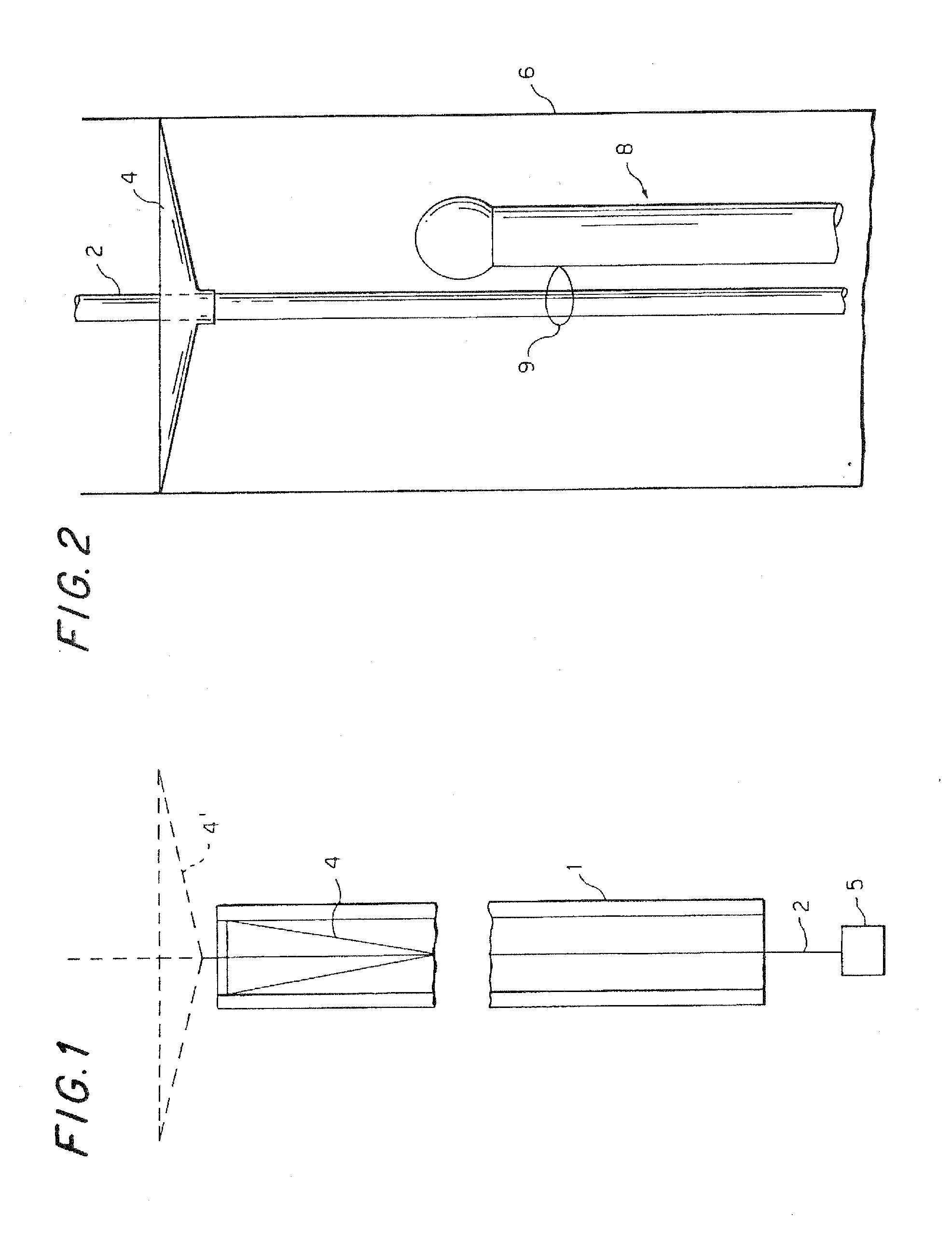
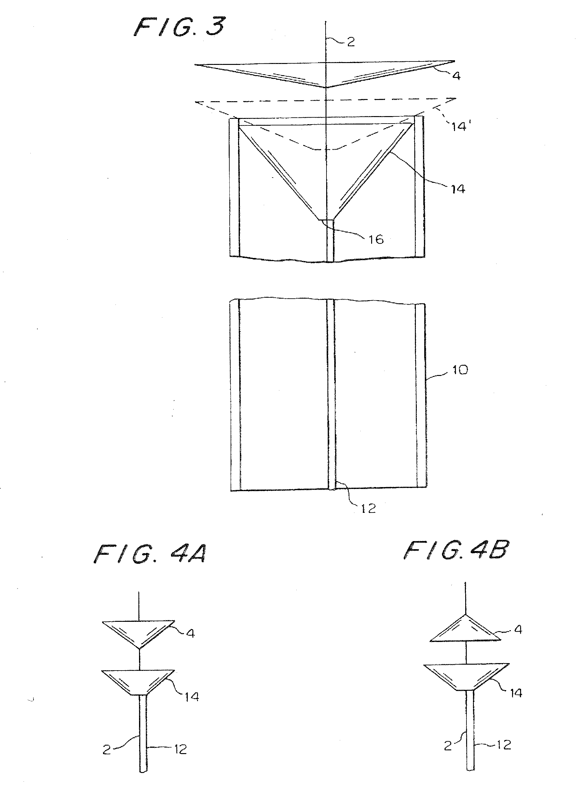
[0039]In the present specification, filters with improved flexibility and smaller profile are described. Such a filter basically has a proximal frame for expansion and contraction and, attached thereto, a thin filter bag that is made of two basic materials. One material is the highly flexible filter membrane itself, with a pattern of holes for allowing flow of blood particles below a well defined size, and the other material is a reinforcement made of fine fibers with high axial strength but thin enough to be flexible upon bending. The reinforcement is integrated with the membrane to create a composite structure with very flexible membrane areas where the...
PUM
Abstract
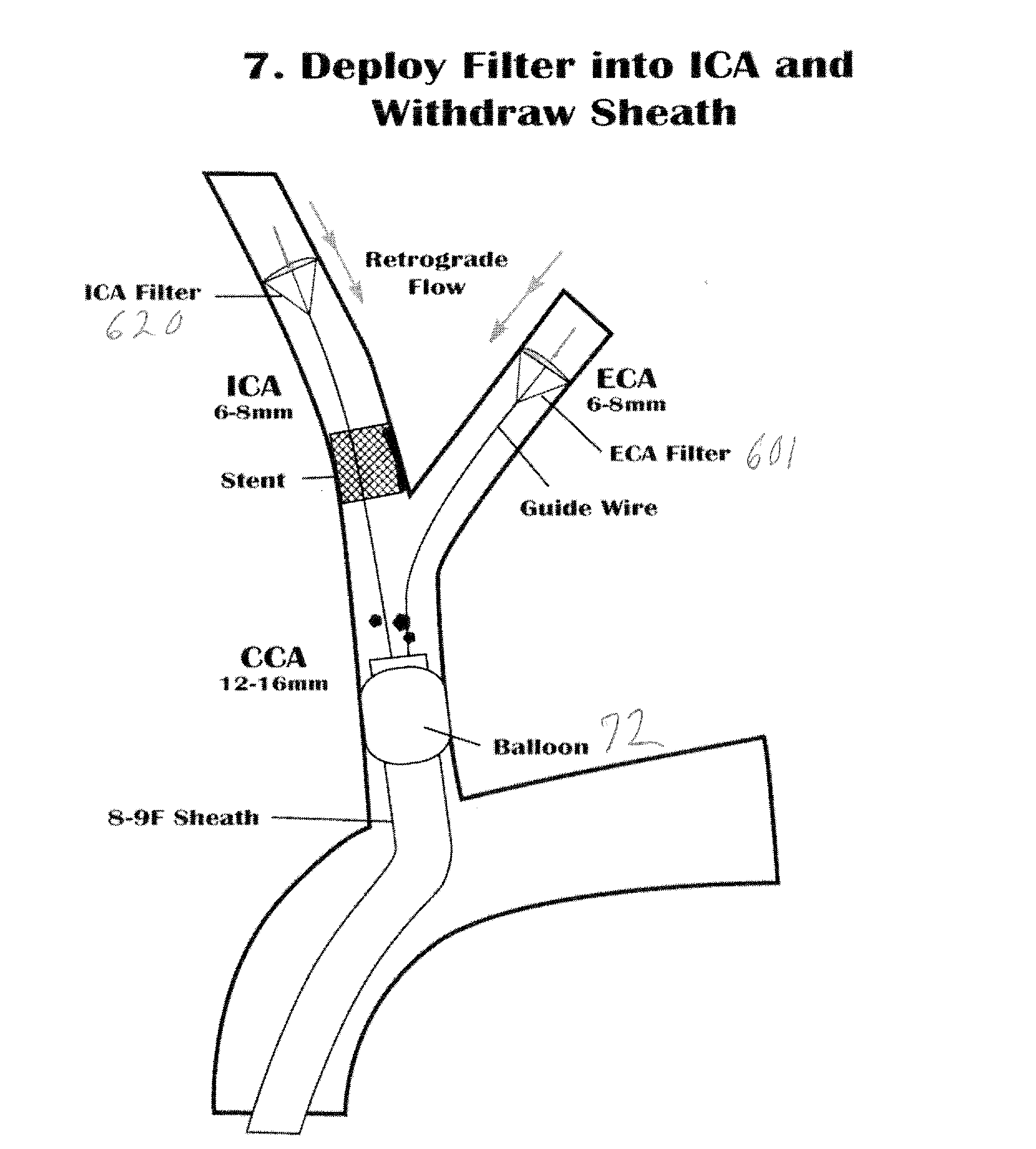
A method and apparatus for treating a patient having an obstruction in a first blood vessel through which blood normally flows in a given direction, at a location downstream of a branch point where the first blood vessel and, a second blood vessel branch off from a main blood vessel, by: blocking blood flow in the main blood vessel at a point upstream of the branch point; inserting into the second blood vessel a first filter adapted to pass blood while trapping debris resulting from removal of the obstruction; inserting an obstruction removal assembly into the first blood vessel and operating the assembly to at least partially break up the obstruction and produce debris; withdrawing the obstruction removal assembly from the patient's body; and then inserting into the first blood vessel a filter adapted to pass blood while trapping debris; then restoring blood flow in the main blood vessel.
Description
[0001]This is a continuation-in-part of allowed U.S. application Ser. No. 10 / 304,067, filed on Nov. 26, 2002, now U.S. Pat. No. 7,214,237, issued on May 8, 2007, which is itself a continuation-in-part of U.S. application Ser. No. 09 / 803,641, filed on Mar. 12, 2002, now U.S. Pat. No. 6,485,502, issued on Nov. 26, 2002, the entire disclosures of which applications and patents are incorporated herein by reference. This application also claims the benefit of the filing dates of the following U.S. Provisional Applications: No. 60 / 412,071, filed Sep. 19, 2002; No. 60 / 417,408, filed Oct. 9, 2002; and No. ______, filed Nov. 1, 2002.BACKGROUND OF THE INVENTION[0002]This invention relates to medical devices, such as vascular filters to be used in a body lumen, such as a blood vessel, with improved strength and flexibility. A filter according to the invention includes a proximal frame section, a distal section and a flexible thin membrane with perfusion holes of a diameter that allows blood to...
Claims
Application Information
Patent Timeline
Application Date:The date an application was filed.
Publication Date:The date a patent or application was officially published.
First Publication Date:The earliest publication date of a patent with the same application number.
Issue Date:Publication date of the patent grant document.
PCT Entry Date:The Entry date of PCT National Phase.
Estimated Expiry Date:The statutory expiry date of a patent right according to the Patent Law, and it is the longest term of protection that the patent right can achieve without the termination of the patent right due to other reasons(Term extension factor has been taken into account ).
Invalid Date:Actual expiry date is based on effective date or publication date of legal transaction data of invalid patent.

