System and method for reinforcing structures

a technology of structure and reinforcement, applied in the field of building methods, can solve the problems of not allowing time for a person, framed wall not having good resistance to forces, and conventional wooden frameworks that do not have much resistance to lateral forces, etc., and achieve the effect of strengthening the structure and increasing the ductility of the structur

Inactive Publication Date: 2009-08-27
FYFE EDWARD R +1
View PDF32 Cites 41 Cited by
  • Summary
  • Abstract
  • Description
  • Claims
  • Application Information

AI Technical Summary

Benefits of technology

[0018]The present invention is a system for reinforcing structures against earthquake, wind, and other strong lateral forces. The system increases the ductility of the structure and strengthens the structure against sudden forces in several directions.
[0021]The ends of the strips are connected to the anchor plates with a plurality of fiber anchors that spread forces and prevent tearing out of the strips. The fiber anchors are lengths of roving that pass through boreholes in the anchor plates and the framing members and are attached with adhesive. The adhered ends of the roving are splayed out to cover a larger area of the plate in order to spread applied forces and prevent tearing out of the anchors.
[0023]The system is quickly applied to an existing wall and requires minimal disruption of the room itself. The materials used are relatively light in weight and do not require special machining or design. The components of the system are applied in an efficient manner that maximizes the reinforcement value of a minimal quantity of materials. The system requires little special equipment and training, thus is suited for use in most countries or regions.
[0025]The system of the present invention greatly increases the resistance of a building to earthquake forces. Use of the reinforcement system also includes the following benefits: increases the ductility of the structure, uses a minimal amount of relatively low-cost and lightweight materials, is appropriate for use in most regions of the world, can be quickly retrofitted in existing buildings with minimum disturbance of occupants and neighbors, and does not spoil the appearance or design of a existing structure.

Problems solved by technology

However, a conventional wooden framework does not have much resistance to the lateral forces that may result from earthquake or high wind.
It is well known that a framed wall does not typically have good resistance to forces normal to the plane defined by the wall.
However, other disasters such as a tornado or earthquake may not allow time for a person to find the strongest location within a structure.
Unfortunately, a great many framed structures that were built in compliance with less stringent codes are still in use and are not expected to be replaced for many years.
Occupants of such structures are endangered during a disaster such as earthquake or tornado by walls being knocked over and the roof subsequently falling down into the structure.
If ductile reinforcement is stressed beyond its capacity, it typically fails in a gradual manner, allowing minutes or even hours for evacuation of the reinforced structure.
A stiff structure frequently fails suddenly and catastrophically, crushing or trapping occupants.
However, a cable support system typically requires the structure to be attached to vacant ground or another feature and may require excavation to install.

Method used


Image

  • System and method for reinforcing structures
  • System and method for reinforcing structures

Examples


Embodiment Construction

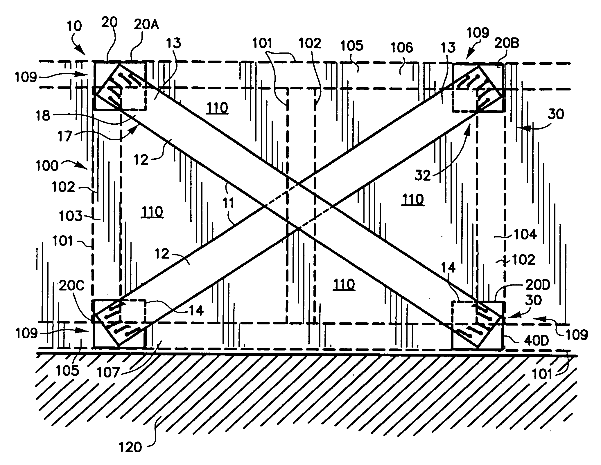
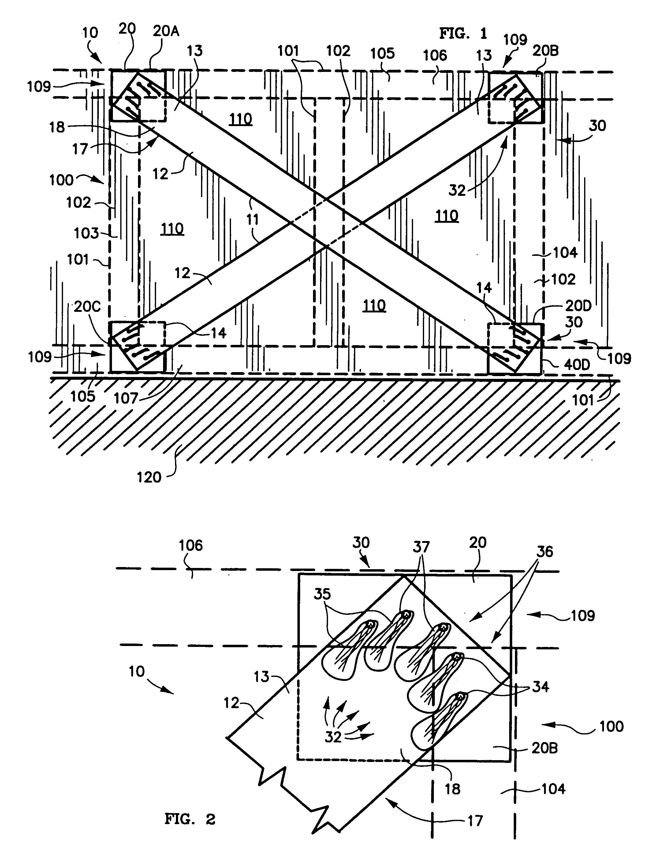
[0029]FIG. 1 is an environmental front elevation view of reinforcement system 10 of the present invention, attached to a conventional framed wall 100. Framed wall 100 consists generally of frame members 101 (shown in phantom) and wall sheathing 110 for covering frame members 101.

[0030]Frame members 101 typically include vertical support members 102, such as first vertical support member 103 and second vertical support member 104. First and second vertical support members 103,104 for a single family house are typically “studs” of soft wood that are nominally 2 inches by 4 inches cross-section and of any needed length, frequently 8 feet.

[0031]Support members 103,104 are parallel and spaced apart from one another. The maximum spacing is usually specified by relevant building code for the region and the type of structure. FIG. 1 indicates an additional support member 102 between first support member 103 and second support member 104.

[0032]Vertical support members 102 must have sufficien...


PUM

PropertyMeasurementUnit
angleaaaaaaaaaa
angleaaaaaaaaaa
lengthaaaaaaaaaa

Abstract

Cost-effective reinforcement system for frames walls helps support against failure from violent lateral forces. Strips of resin-impregnated textile in crossed pairs are attached to frame members. Attachment of ends of strips is ductile due to use of multiple fiber anchors.

Description

FIELD OF THE INVENTION[0001]The present invention relates to building methods, and more particularly to a method of reinforcing structures against lateral forces that is well suited to retrofit of existing wood-framed buildings.BACKGROUND OF THE INVENTION[0002]Many modern buildings, including most residences, are supported by a framework consisting of an array of vertical support members connected at top and bottom by horizontal connecting members. The most familiar example of this type of construction in the United States is the wooden frame house with 2×4 wooden studs connected by a wooden bottom plate at the bottom and a wooden top plate at the top.[0003]The bottom plate connects the frame to the foundation and the top plate connects to the roof. The studs are typically attached to the top and bottom plates by stiff attachment means such as nails or screws. The wooden framework provides the compressive strength sufficient to support the weight of the walls and roof. However, a co...

Claims


Application Information

Patent Timeline
Patent Type & Authority Applications(United States)
IPC IPC(8): E04C2/38E04C5/07E04G21/28
CPCE04C2/386E04G23/0218E04C2003/026E04G2023/0248E04G2023/0251
Inventor FYFE, EDWARD R.JAMAJI, RUSTOM
Owner FYFE EDWARD R
Why Eureka
Try Eureka