Reinforcement device for supporting structures

Inactive Publication Date: 2005-02-08
SIKA SCHWEIZ AG
View PDF10 Cites 72 Cited by
  • Summary
  • Abstract
  • Description
  • Claims
  • Application Information

AI Technical Summary

Benefits of technology

Hence, the goal of the present invention is to provide a CFK reinforcing panel in which the introduction of force from the beam into the ends takes place in such fashion that separation becomes practically impossible and which is also suitable for pretensioning.
This goal is achieved by splitting the ends of a CFK panel into at least two and preferably three or more end; strips. In this way, the surface for connection to an end element is increased considerably. As a result, there is a good initiation of the force into the ends of t

Problems solved by technology

Problems, and especially corrosion problems, arise when supporting structures such as bridge beams are to be reinforced in this manner in the open.
Because of the relatively high weight and the production of such steel panels, the maximum length that can be used is limited.
Likewise, for reasons of space, installation in closed spaces can be problematic when the rigid steel panels cannot be transported into the space in question.
This also results in high cost.
Clamping means of this kind are conventionally included when planning the supporting structure, because retrofitting is practically impossible or can be done only at very high cost, since corresponding channels in the supports must

Method used


Image

  • Reinforcement device for supporting structures
  • Reinforcement device for supporting structures
  • Reinforcement device for supporting structures

Examples


Embodiment Construction

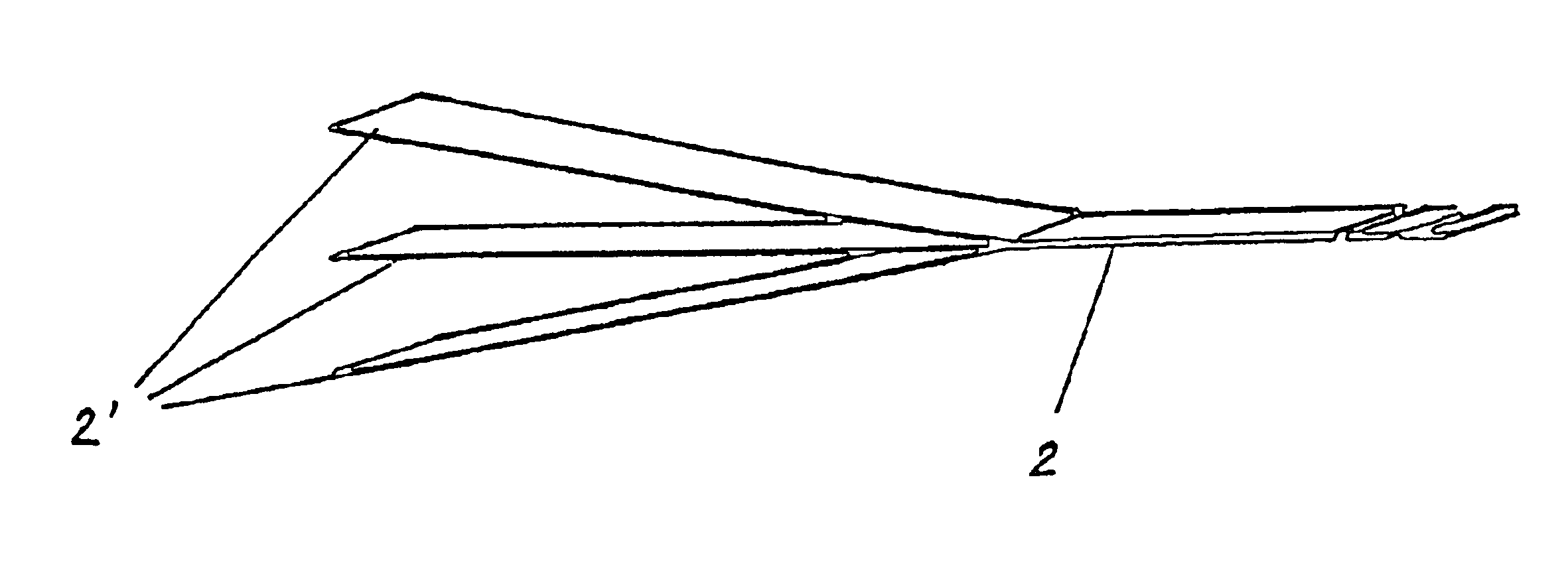
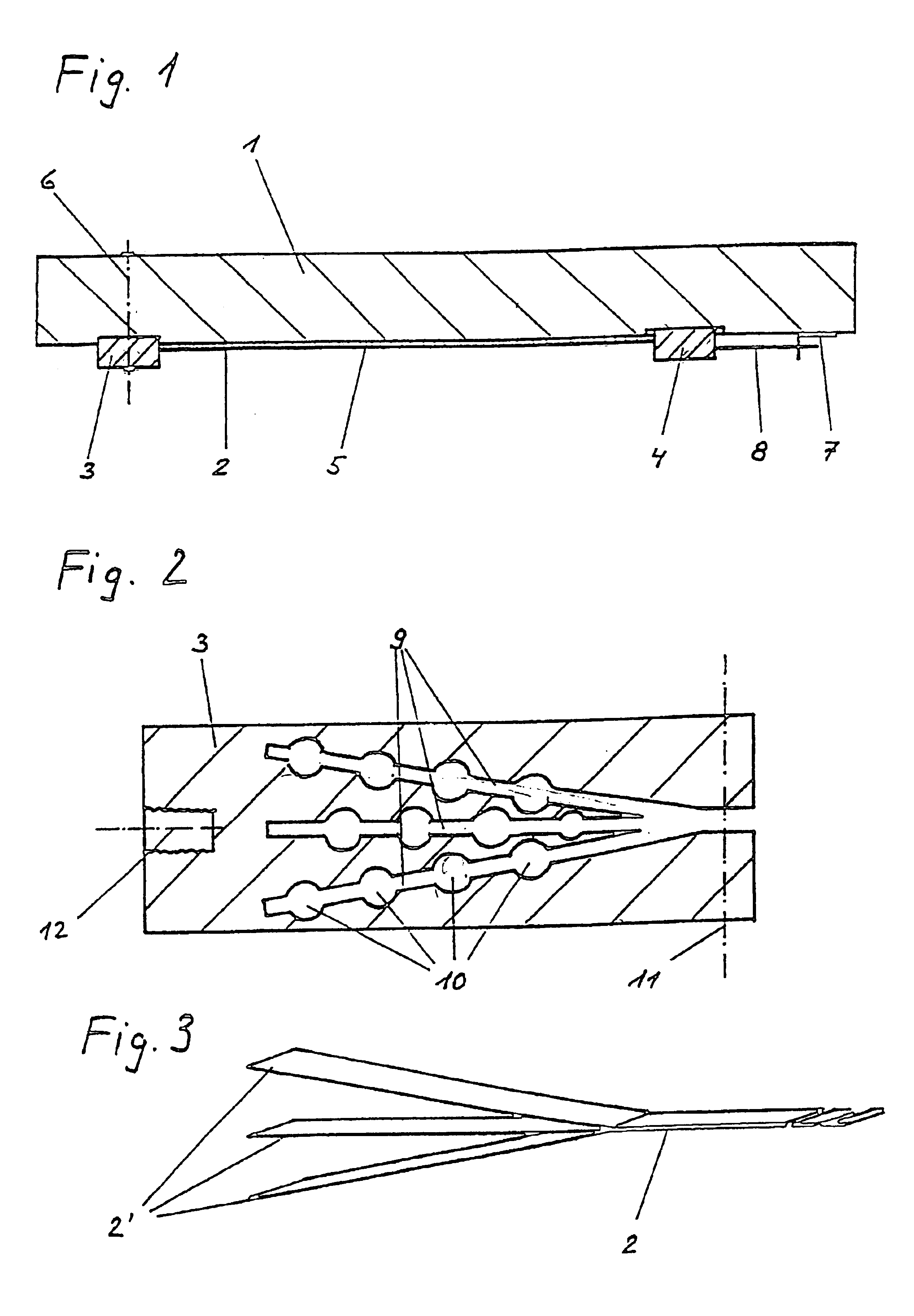
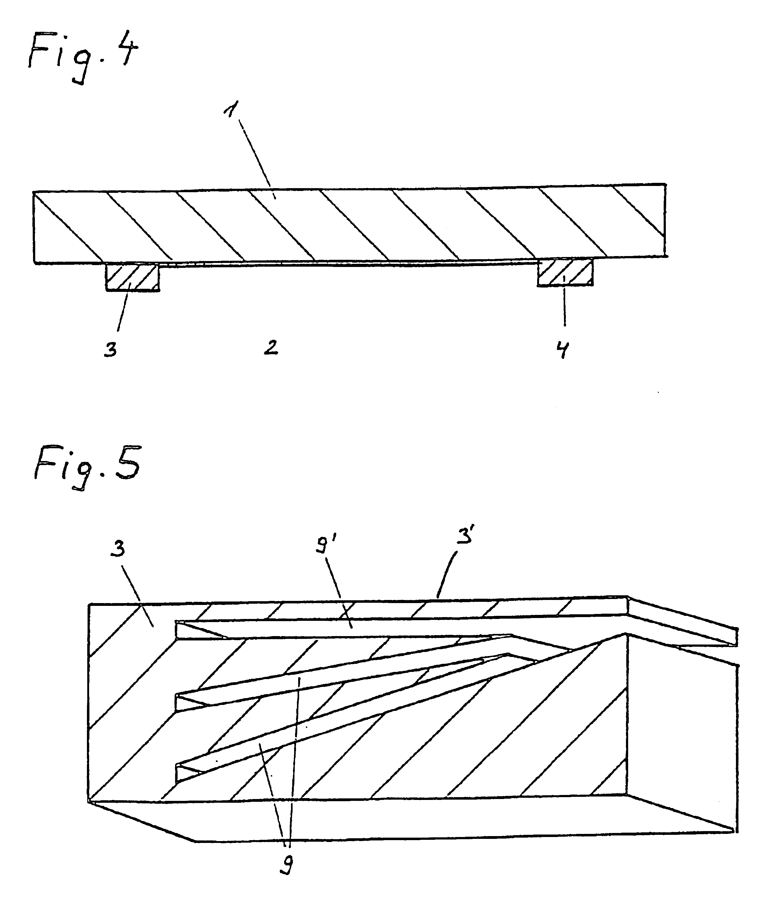
FIG. 1 shows a cross section through a beam 1 to be reinforced. The ends of the CFK panel 2 used for this purpose are inserted according to the invention in elements, in this case anchor heads 3 and 4. Anchor heads 3 and 4 can be inserted into milled or pointed recesses of beam 1 as shown in this figure. CFK panel 2 is connected with beam 1 over part or all of the area by a layer of adhesive 5 and the anchor heads 3 and 4 are glued to it as well. In addition, anchor heads 3 and 4 can be connected with the beam by a transverse clamping device 6, shown here simply schematically, resulting in an improved direction of the force through the anchor heads 3 and 4 from the CFK panel 2 into the beam 1. This transverse clamping device 6 can be for example, a threaded rod or dowel guided through the beam 1 and the anchor heads 3 and 4.

The reinforcing device composed of the CFK panel 2 and the anchor heads 3 and 4 can also be simply pretensioned as shown schematically on the right-hand side of ...


PUM

PropertyMeasurementUnit
Thicknessaaaaaaaaaa
Angleaaaaaaaaaa
Widthaaaaaaaaaa

Abstract

The ends of carbon plates reinforcing supporting elements, such as concrete beams, are divided into at least two splines having approximately the same thickness and are glued in the appropriate retaining slots of a terminal element. The splines form an angle in relation to each other. This assembly is then glued to the traction side of the supporting element, whereby the carbon plates are directly prestressed by the terminal elements in relation to the supporting element. The terminal element can be inserted into an appropriate groove in the supporting element or glued directly on the surface of the supporting element and/or doweled, optionally by using a transverse tensioning device.

Description

BACKGROUND AND SUMMARY OF THE INVENTIONThe present invention relates to a reinforcing device as well as a method for reinforcing beams.When rehabilitating supporting structures in existing buildings, the supporting structures often are to be adapted for new load cases that exceed the former dimensions. In order to avoid replacing a supporting structure completely in such cases, methods and devices for reinforcing such an existing supporting structure have been found. Such supporting structures can be walls of conventional design made of brick, reinforced concrete walls or beams, or beams made of wood, plastic, or steel, for example.Reinforcement of such supporting structures with steel plates added later has been known for a long time. The steel plates, namely strips of sheet steel or steel panels, are glued to one or both sides of the supporting structure, preferably on the side of the supporting structure subjected to tension. The advantage of this method is that it can be impleme...

Claims


Application Information

Patent Timeline
IPC IPC(8): E04G23/02E04C3/26E04C5/07E04C3/20E04C5/12
CPCE04C3/26E04C5/07E04G23/0218E04C5/127Y10T156/1059E04G2023/0251E04G2023/0259E04G2023/0262
Inventor SCHWEGLER, GREGOR
Owner SIKA SCHWEIZ AG
Why Eureka
Try Eureka