Automatic welding wire feed adjuster

a feed adjuster and wire technology, applied in welding equipment, arc welding equipment, manufacturing tools, etc., can solve problems such as erratic welding arc, deformation of wires, and rollers

Active Publication Date: 2008-12-04
LINCOLN GLOBAL INC
View PDF10 Cites 41 Cited by
  • Summary
  • Abstract
  • Description
  • Claims
  • Application Information

AI Technical Summary

Problems solved by technology

Unfortunately, if the tension between rollers 14 is set too high, the rollers 14 will deform the wire 35 as it passes therethrough.
On the other hand, if the pressure between rollers 14 is set too low, wire 35 will be fed to gun 22 at an erratic rate, which results in an erratic welding arc and poor weld quality.

Method used


Image

  • Automatic welding wire feed adjuster
  • Automatic welding wire feed adjuster
  • Automatic welding wire feed adjuster

Examples


Embodiment Construction

[0027]Exemplary embodiments of the invention will now be described below by reference to the attached Figures. The described exemplary embodiments are intended to assist the understanding of the invention, and are not intended to limit the scope of the invention in any way. Like reference numerals refer to like elements throughout.

[0028]In an exemplary embodiment of the invention, an automatic feed adjuster is utilized to provide optimized wire feeding and welding.

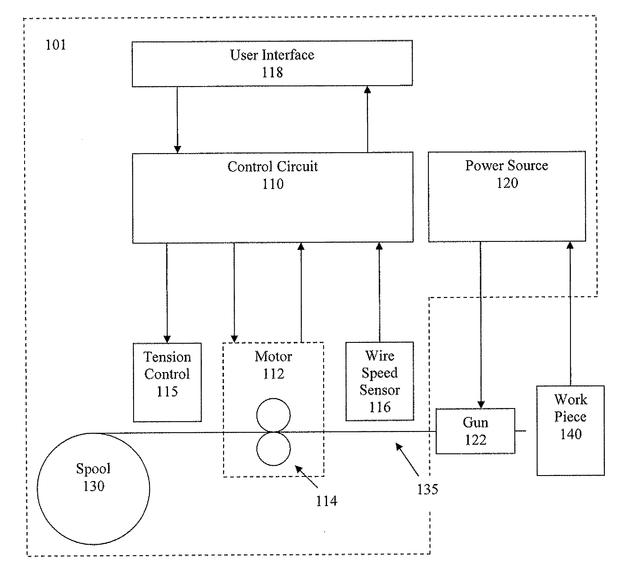
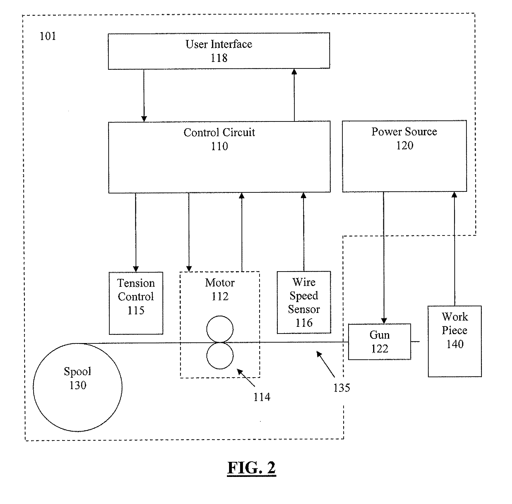
[0029]More specifically, as shown in FIG. 2, welding system 101 includes control circuit 110, power source 120, motor 112, tension control 115, wire speed sensor 116, user / data interface 118, and spool 130. Spool 130 contains wire 135 spooled thereon. Motor 112 drives opposing rollers 114 to take up wire 135 from spool 130 and send it to gun 122. The operator utilizes gun 122 to form a weld on workpiece 140. As the weld is formed on workpiece 140, wire 135 is consumed, and is replaced by motor 112.

[0030]User / data interface...


PUM

PropertyMeasurementUnit
tensionaaaaaaaaaa
speedaaaaaaaaaa
diameteraaaaaaaaaa

Abstract

An automatic wire feed adjuster, including a feeding mechanism including a pair of rollers that feeds a wire therebetween, a tension controller that adjusts a tension between the pair of rollers, a wire speed sensor that measures a fed speed of the wire after exiting the feeding mechanism, and a control circuit that compares a driven speed of the wire with the fed speed of the wire, and that decides whether to instruct the tension controller to adjust the tension between the pair of rollers.

Description

BACKGROUND OF THE INVENTION[0001]1. Field of the Invention[0002]Devices, systems, and methods consistent with the invention relate to an automatic feed adjuster.[0003]2. Description of the Related Art[0004]In the related art, there are various types of welding processes, including processes which utilize a continuous wire feed as a welding electrode.[0005]A diagrammatical representation of such a related art continuous wire feed welding process is illustrated in FIG. 1. In FIG. 1, a welding system 1 includes a control circuit 10, a power source 20, a motor 12, and spool 30. Spool 30 contains wire 35 spooled thereon. Motor 12 drives opposing rollers 14 to take up wire 35 from spool 30 and send it to gun 22. The operator utilizes gun 22 to form a weld on workpiece 40. As the weld is formed on workpiece 40, wire 35 is consumed at gun 22, and is replaced by feeding more wire 35 to gun 22 by action of motor 12 and rollers 14 at a constant rate.[0006]Different types of wires 35 are availa...

Claims


Application Information

Patent Timeline
Patent Type & Authority Applications(United States)
IPC IPC(8): B23K9/12
CPCB23K9/124
Inventor MECKLER, ANDREU P.
Owner LINCOLN GLOBAL INC
Why Eureka
Try Eureka