Artistic Flat Panel Concealment Screen

Inactive Publication Date: 2008-12-04
COOPER CATHRYN
View PDF16 Cites 17 Cited by
  • Summary
  • Abstract
  • Description
  • Claims
  • Application Information

AI Technical Summary

Benefits of technology

[0007]In one embodiment, the panels of the invention align when unfolded to a closed position or configuration to create a larger, virtual panel, or screen, which conceals the video display device when not in use. Hinges interconnect the panels to enable an alternating, or “accordion style”, folding of the panels. Hinges connect the panels to the edges of the concealment box and allow the panels to fold clear of the display device providing full access to the device.
[0008]The enclosure or concealment box for the display device may be of various forms including recessed into a wall or as a structure mounted to an existing surface. This enclosure may be a shallow “frame” f

Problems solved by technology

Flat panel display devices have decreased some of the space requirements for large viewing area video devices, yet they have not addressed the height and

Method used


Image

  • Artistic Flat Panel Concealment Screen
  • Artistic Flat Panel Concealment Screen
  • Artistic Flat Panel Concealment Screen

Examples


Embodiment Construction

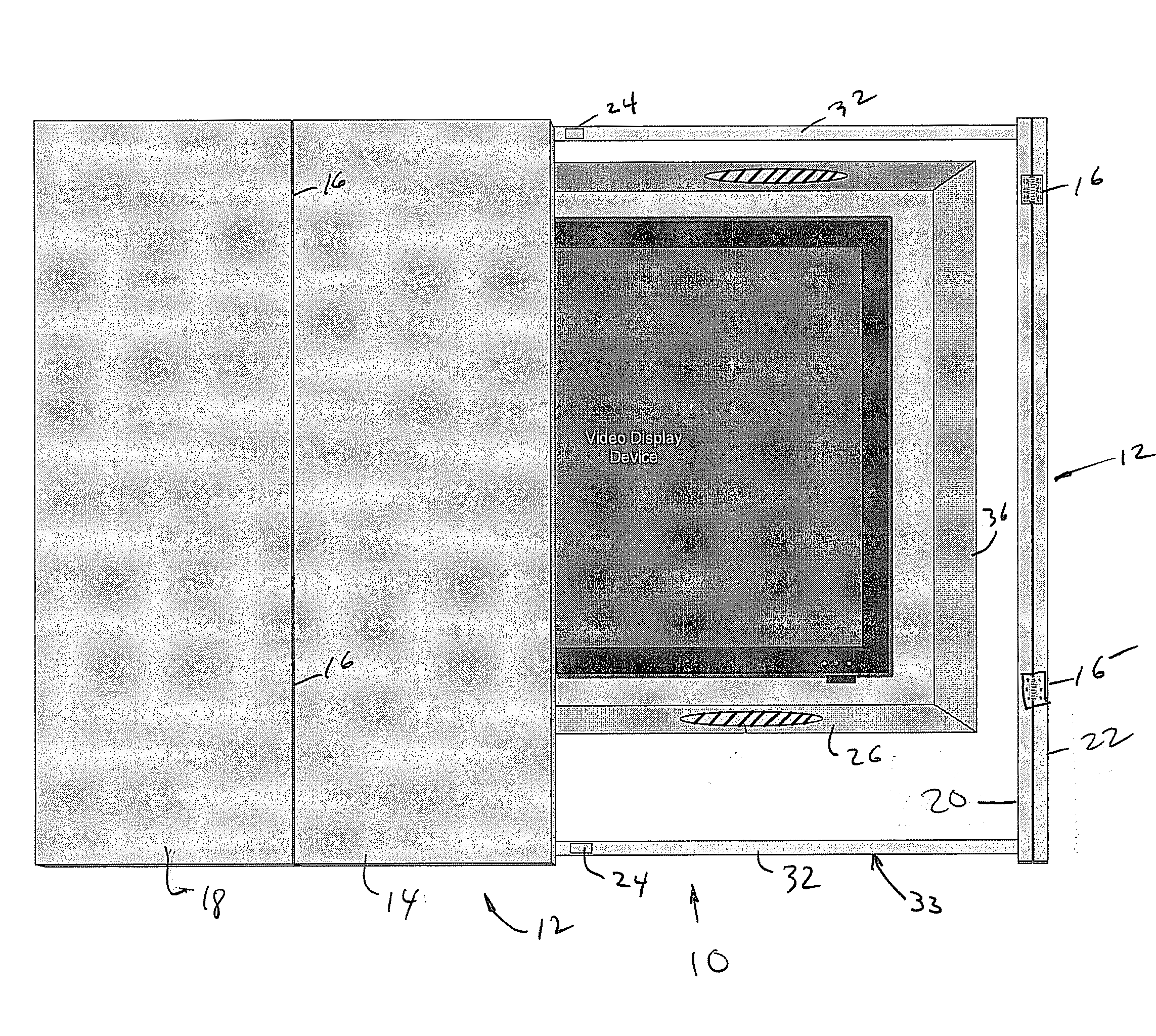
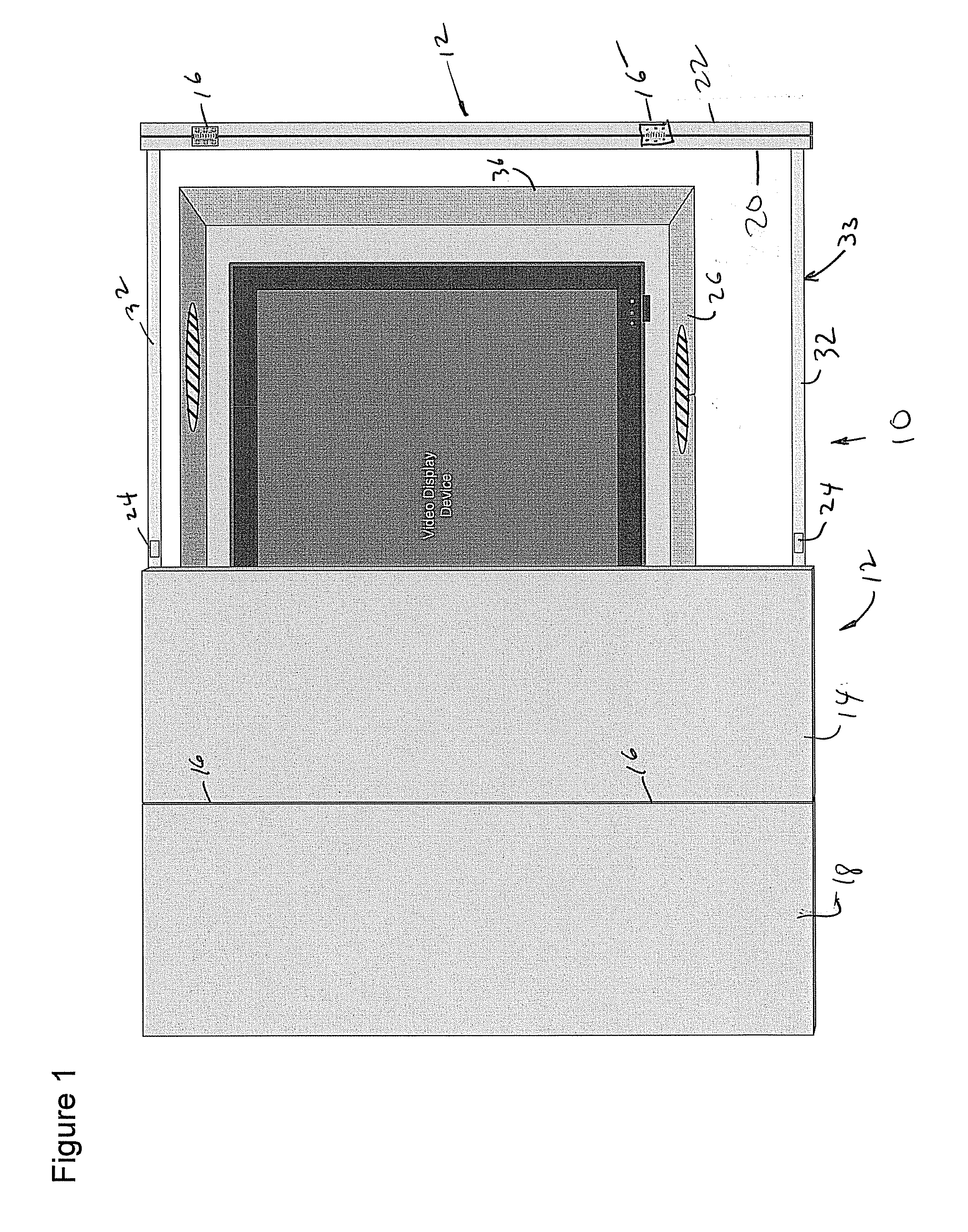
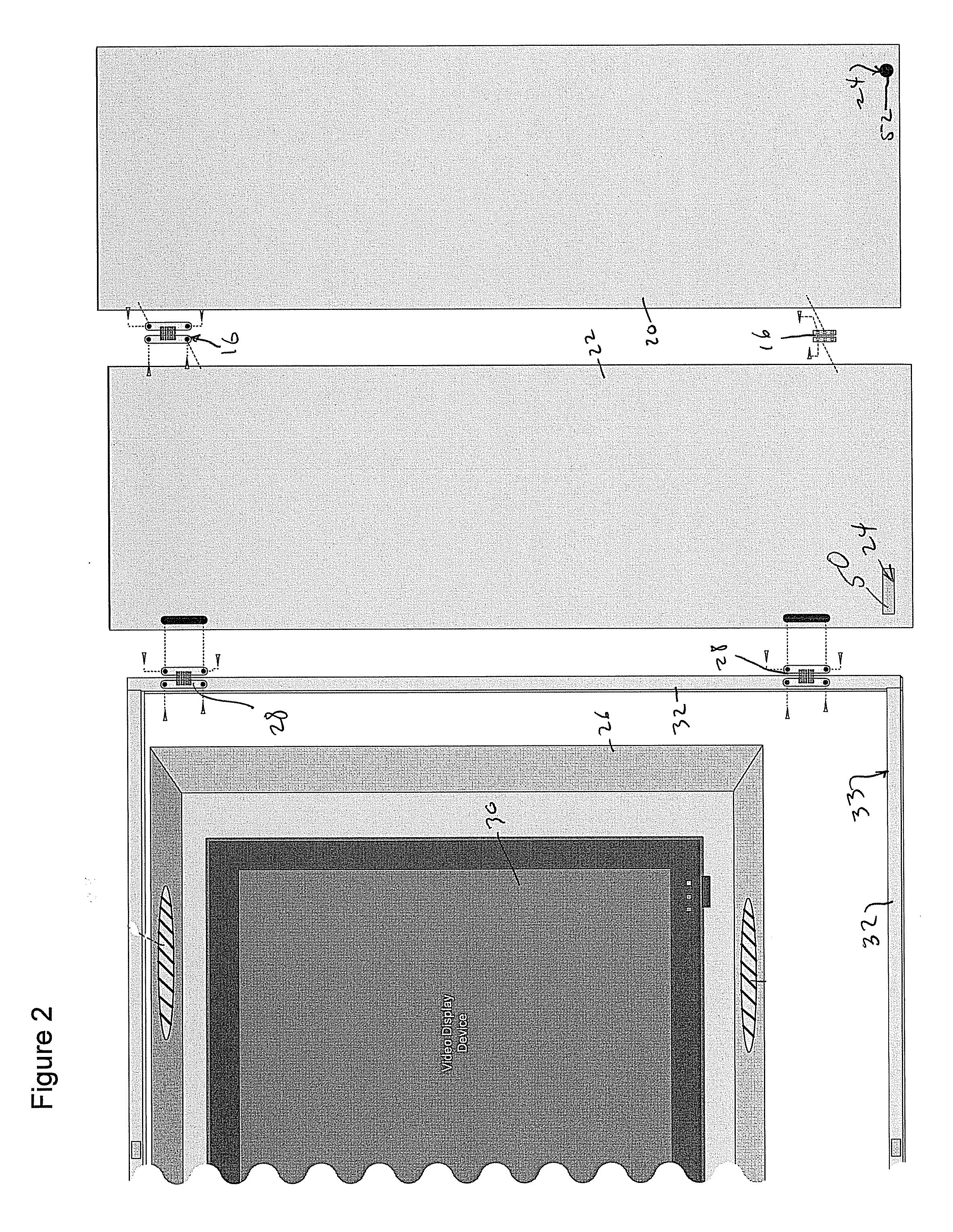
[0015]Referring to FIGS. 1-3, an embodiment of the invention is a concealment screen assembly 10, which generally includes one or more image panels 12. FIG. 1 shows four separate, but pivotally interconnected image panels including a first inner panel 14 attached by a pair of panel hinges 16 to a first outer panel 18. A second inner panel 20 is attached to a second outer panel 22 by a similar pair of panel hinges 16. Panel hinges 16 are attached between adjacent panels 14, 18 and 20, 22 and function to pivotally connect panels. Examples of hinges 16 include a standard bi-fold hinge and preferably, a full 180-degree hidden hinge or any suitable hinge. As shown at 16′, the hinges 16 may be covered to hide the hinge mechanism, for example, with a cloth material.

[0016]It will be understood that panels 12 may be a single panel, or two or more panels. Each of the panels 12 may have an entire image, or part of an image displayed thereon. Alternately, the panels 12 may include a plain surfa...


PUM


Abstract

An artistic flat panel concealment screen is shown for discretely concealing a display device or the like, when the device is not in use. The invention can be articulated using a set of panels and mechanical hinges, which expose the display device for use when the invention is in the “open” position. In the open position, the panels are permitted to fold out of the way and preferably flat against an adjacent surface through use of riser plates. When the display is not in use, the panels of the invention can be “closed” to conceal the unused display device behind a piece of “art” or décor that is applied to the outside of the panels. The panels of the invention span a concealment box that is used to surround the display device and provide the enclosure for the device. The concealment box may either be an external structure mounted to the surface of an existing wall or may be a recess into a wall or other structure of a building such as a bookshelf or furniture piece.

Description

[0001]This claims the benefit of Provisional Application No. 60 / 941,180, filed May 31, 2007.BACKGROUND OF THE INVENTION[0002]The invention relates to the incorporation of home electronics into a living environment, and more particularly, addresses how increasingly larger display surfaces including all home electronics can be integrated into the environment with minimal disruption to the interior décor when the display device is not in use.BRIEF SUMMARY OF THE INVENTION[0003]Flat panel display devices have decreased some of the space requirements for large viewing area video devices, yet they have not addressed the height and width of the actual viewing area or the aesthetic impact of the display surface on the aesthetic of a living space when the display device is not in use. While the most common application of the invention is intended for the concealment of flat panel (e.g. Liquid Crystal Display, Plasma, etc.) video devices, both traditional cathode ray rube displays as well as ...

Claims


Application Information

Patent Timeline
IPC IPC(8): A47B81/06
CPCA47B81/06
Inventor COOPER, CATHRYN
Owner COOPER CATHRYN
Why Eureka
Try Eureka