Liquid-droplet ejecting apparatus
a technology of liquid droplets and ejectors, which is applied in the direction of instruments, printing, optics, etc., can solve the problems of inability to perform gas or air suction from the sub-tank, inhibiting the separation of gas or air bubbles from ink, and undesirable inflow of gas or air
- Summary
- Abstract
- Description
- Claims
- Application Information
AI Technical Summary
Benefits of technology
Problems solved by technology
Method used
Image

Examples
first embodiment
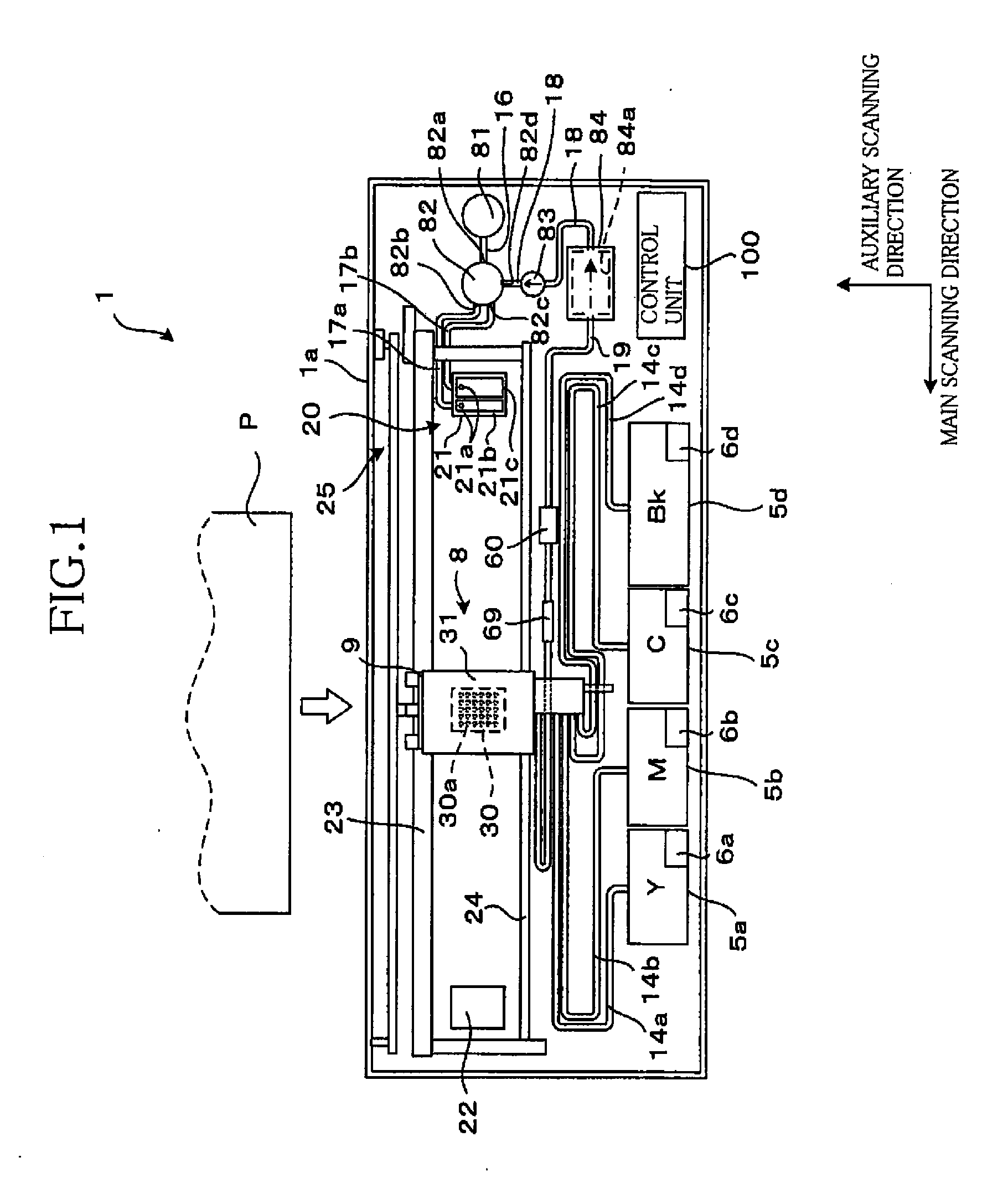
[0081]With reference to FIGS. 1-11, there will be described an inkjet printer according to the invention. FIG. 1 is a schematic plan view of the inkjet printer denoted by reference numeral 1. In the following description, a main scanning direction and an auxiliary scanning direction are a lateral direction and a vertical direction as seen in FIG. 1, respectively.
[0082]The inkjet printer 1 includes an inkjet head 8 as a form of a liquid ejecting head of the invention. The inkjet head 8 ejects droplets of ink as a form of a liquid of the invention. The inkjet head 8 has a carriage 9 and a head mainbody 30 fixed on the carriage 9. At a lower or under surface of the head mainbody 30 are formed a plurality of nozzles 30a (as ejection openings), from which ink droplets are ejected. The head mainbody 30 is fixed on the carriage 9 with the nozzles 30a exposed or open downward. On an upper surface of the head mainbody 30, a sub tank 31 (described later) is fixed.
[0083]In the inkjet printer 1...
fifth embodiment
[0155]Referring to FIGS. 17-19, there will be described an inkjet printer according to the invention, which is generally denoted by reference numeral 401. In FIG. 17, a part of an internal structure of a carriage 9 of the inkjet printer 401 is indicated by broken line, but a head mainbody 30, ink storage chambers 41-44, and others disposed in a lower portion of the carriage 9 are not shown for facilitating comprehension.
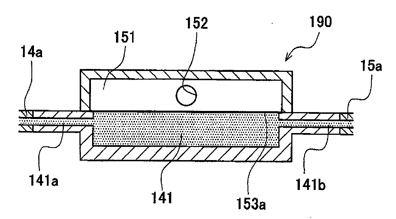
[0156]Unlike the inkjet printer 1 of the first embodiment, the inkjet printer 401 of the sixth embodiment does not include the pressure limiter 69, but includes a pressure control device 90 instead. Similar to the first embodiment, in this embodiment when an internal pressure of an air chamber 51 becomes equal to or higher than a predetermined first threshold, a suction pump 81 sucks the air from the air chamber 51 so as to decrease the internal pressure thereof below the first threshold. At this time, there is a possibility that the internal pressure of the air cham...
sixth embodiment
[0160] when the internal pressure of the pressure control chamber 91 of the pressure control device 90 becomes lower than the second threshold, the port 91c is opened. Since the port 91c is in communication with the external space of the inkjet head 408 through the air tube 75, the void 471a of the heatsink 471, the air tube 76, and the mist catching device 77, the air is introduced from the external space of the inkjet head 408 into the pressure control chamber 91 from the port 9c, to increase the internalpressure of the air chamber 51. When the thus increased internal pressure of the air chamber 51 becomes equal to or higher than the second threshold, the port 91c is closed and the internal pressure of the pressure control chamber 91 stops rising. Thus, even when the internal pressure of the air chamber 51 decreases below the second threshold, for instance due to excessive sucking of the air chamber 51 during an air-chamber suction processing, the pressure control device 90 operat...
PUM
 Abstract
Description
Claims
Application Information
 - R&D Engineer
- R&D Manager
- IP Professional
- Industry Leading Data Capabilities
- Powerful AI technology
- Patent DNA Extraction
Browse by: Latest US Patents, China's latest patents, Technical Efficacy Thesaurus, Application Domain, Technology Topic.
© 2024 PatSnap. All rights reserved.Legal|Privacy policy|Modern Slavery Act Transparency Statement|Sitemap