Movement preventing structure for color separation prism

a color separation prism and structure technology, applied in the direction of mountings, instruments, optics, etc., can solve the problem that the movement of the color separation prism cannot be prevented

Inactive Publication Date: 2008-12-04
SONY CORP +1
View PDF1 Cites 1 Cited by
  • Summary
  • Abstract
  • Description
  • Claims
  • Application Information

AI Technical Summary

Benefits of technology

[0013]According to the second aspect of the present invention, since the length in an optical axis direction of the color separation prism movement preventing member is set so that the distance of movement of the color separation prism caused by the thermal expansion or contraction of the color separation prism movement preventing member and the distance of movement of the color separation prism caused by the thermal expansion or contraction of the color separation prism supporting member are approximately equal to each other, the movement in an optical axis direction of the color separation prism caused by the thermal expansion or contraction of the color separation prism supporting member can further be prevented or reduced.
[0014]According to the present invention, the movement in an optical axis direction of the color separation prism caused by the thermal expansion or contraction of the color separation prism supporting member can be prevented or reduced.

Problems solved by technology

The camera apparatus of this type has a problem in that the color separation prism supporting member thermally expands or contracts due to a change in outside air temperature at the time of photographing, and thereby the color separation prism is moved in an optical axis direction.
Therefore, there arises a problem in that even if this mechanism is applied to various types of camera apparatuses for motion picture photography, each of which has a color separation prism supported by the color separation prism supporting member, the movement of the color separation prism cannot be prevented.

Method used


Image

  • Movement preventing structure for color separation prism
  • Movement preventing structure for color separation prism
  • Movement preventing structure for color separation prism

Examples


Embodiment Construction

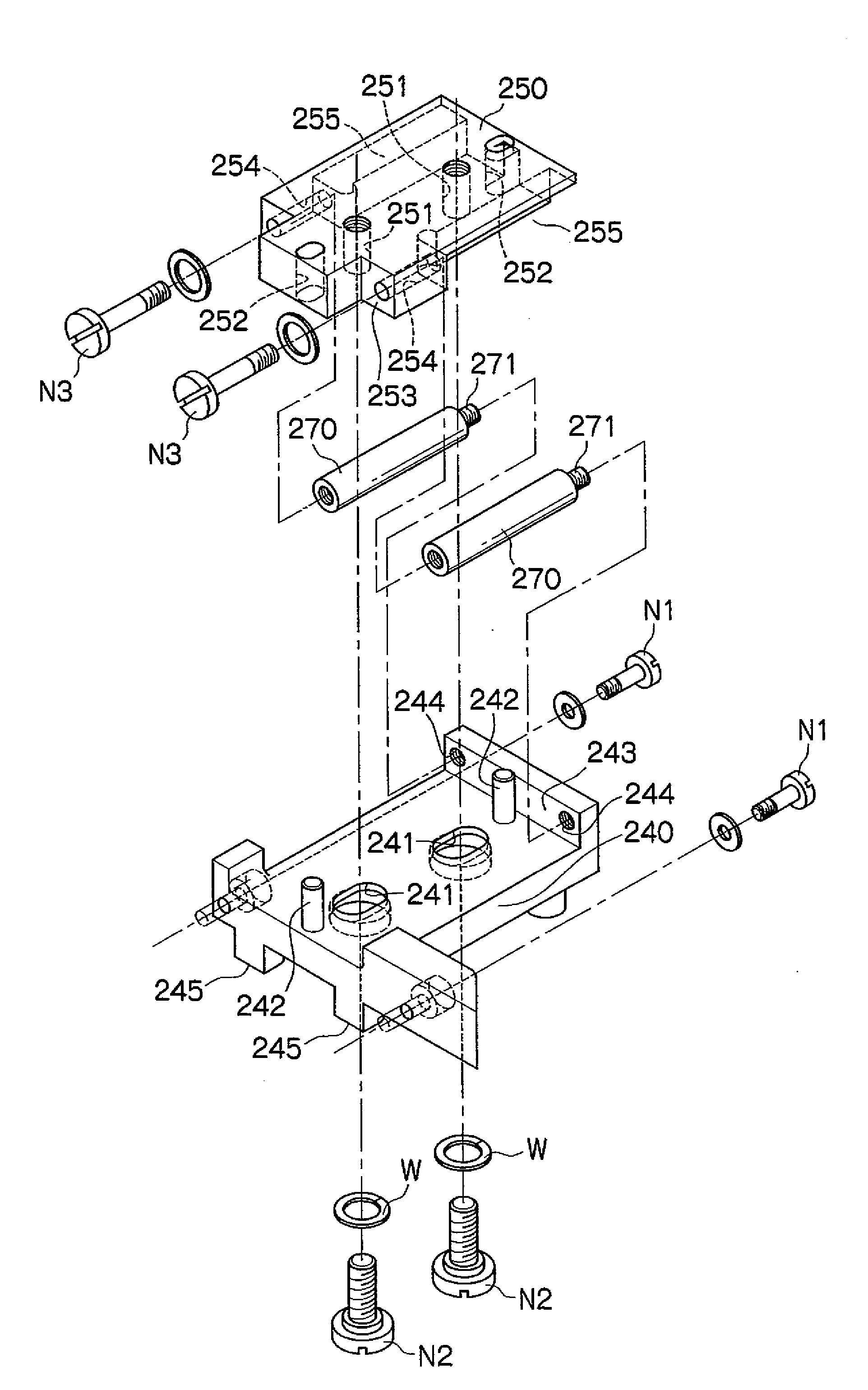
[0018]A movement preventing structure for a color separation prism in accordance with one embodiment of the present invention will now be described with reference to the accompanying drawings.

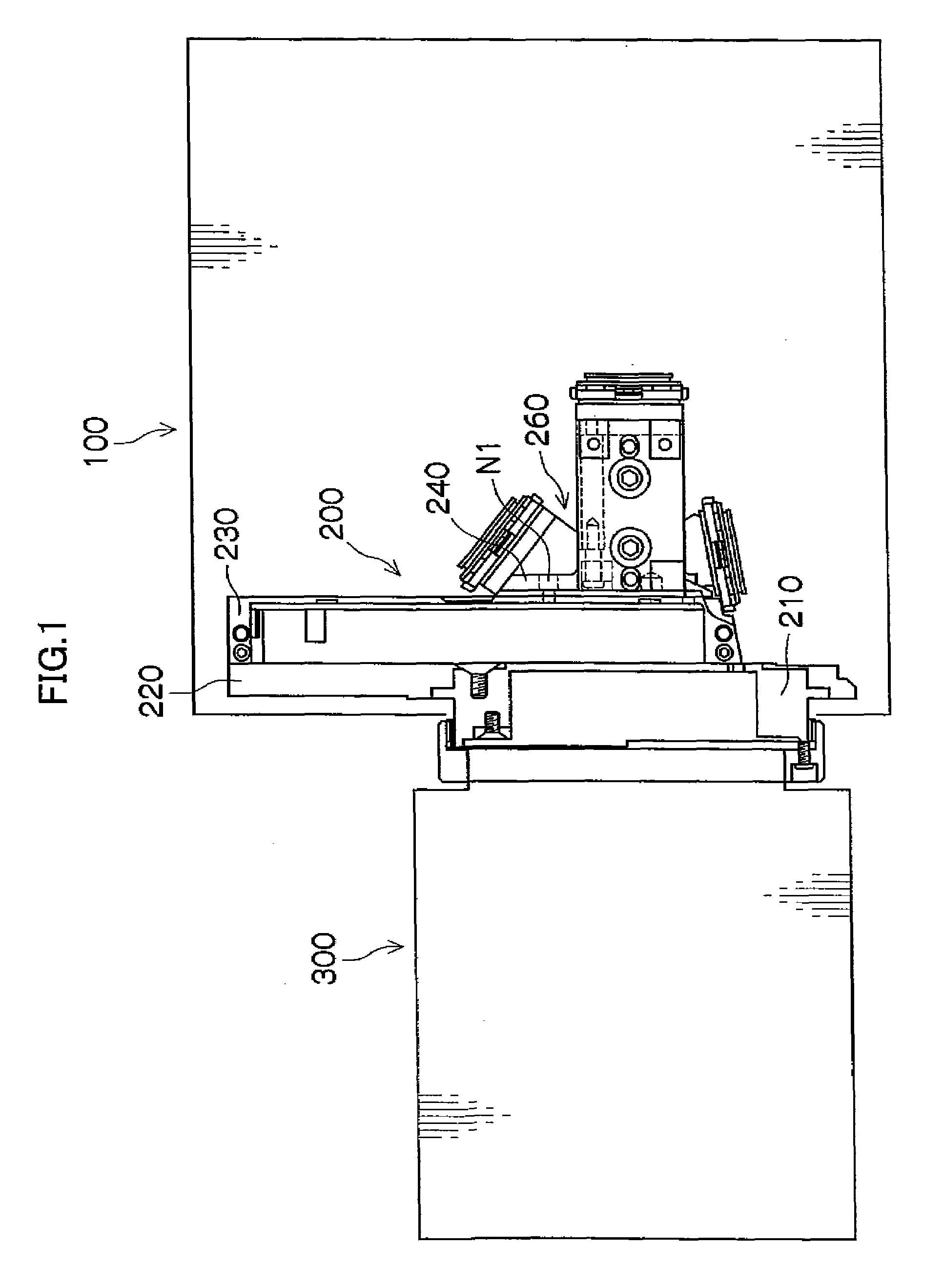
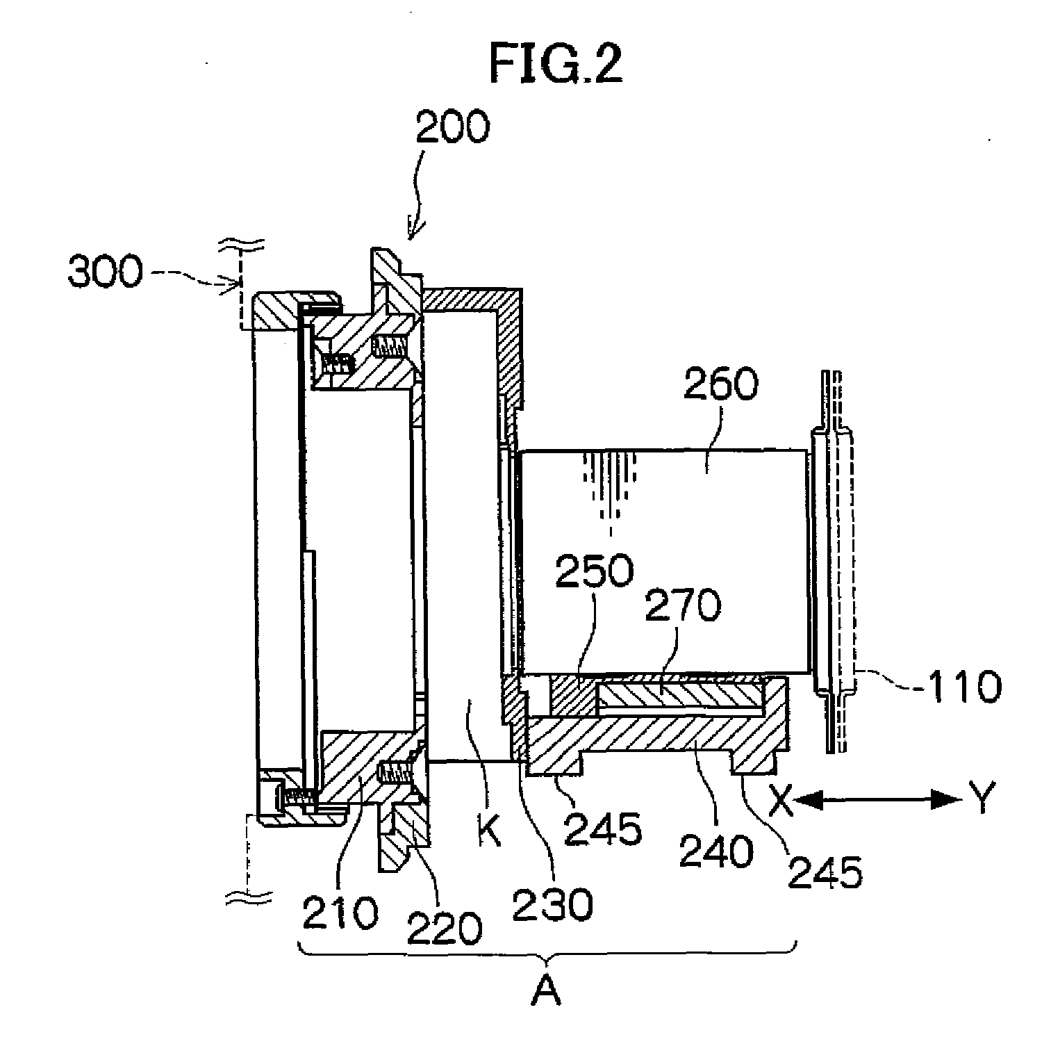
[0019]FIG. 1 is a side view for explaining a camera apparatus body to which the movement preventing structure for a color separation prism in accordance with one embodiment of the present invention is applied, and a lens apparatus mounted on the camera apparatus body. FIG. 2 is a sectional view for explaining the configuration of a color separation prism unit mounted on the camera apparatus body shown in FIG. 1.

[0020]As shown in FIG. 1, the movement preventing structure for a color separation prism of this embodiment is applied to the color separation prism unit 200, which is mounted on the camera apparatus body 100 by screwing etc., or the like.

[0021]The color separation prism unit 200 is a unit that is fixed at a predetermined location of the camera apparatus body 100 by screwing etc. to form...


PUM


Abstract

A movement preventing structure for a color separation prism prevents or reduces the movement in an optical axis direction of the color separation prism caused by the thermal expansion or contraction of a color separation prism supporting member. In the movement preventing structure for a color separation prism, in which the movement in an optical axis direction of the color separation prism is prevented by the thermal expansion or contraction of the color separation prism supporting member which supports the color separation prism arranged between a mount part, on which a lens apparatus is detachably mounted, and a solid-state image sensing element of a camera apparatus having the mount part and the solid-state image sensing element, the movement preventing structure has a color separation prism movement preventing member being formed of a thermally-expanding material, having a first fixing part fixed to the color separation prism and a second fixing part fixed to the color separation prism supporting member, and the length in an optical axis direction thereof being changed by thermal expansion or contraction; the color separation prism supporting member supports the color separation prism so that the color separation prism is movable in an optical axis direction; and the length in an optical axis direction of the color separation prism movement preventing member is changed by thermal expansion or contraction, and the color separation prism movement preventing member applies a force to the color separation prism fixed in the first fixing part, whereby the color separation prism is moved in the direction reverse to the direction of the movement of the color separation prism caused by the thermal expansion or contraction of the color separation prism supporting member.

Description

BACKGROUND OF THE INVENTION[0001]1. Field of the Invention[0002]The present invention relates to a movement preventing structure for a color separation prism, and more particularly, to a movement preventing structure for a color separation prism which is applied to a camera apparatus having the color separation prism supported by a color separation prism supporting member whose length in an optical axis direction is changed by thermal expansion or contraction.[0003]2. Description of the Related Art[0004]Conventionally, there has been known various types of camera apparatuses for motion picture photography, each of which has a color separation prism supported by a color separation prism supporting member. The camera apparatus of this type has a problem in that the color separation prism supporting member thermally expands or contracts due to a change in outside air temperature at the time of photographing, and thereby the color separation prism is moved in an optical axis direction. ...

Claims


Application Information

Patent Timeline
Patent Type & Authority Applications(United States)
IPC IPC(8): G02B7/18
CPCG02B7/1805G02B27/141
Inventor SAKATA, NORIAKIKIGA, KAZUYOSHIKOBAYASHI, TADASU
Owner SONY CORP
Why Eureka
Try Eureka