
Glass Substrate Protective Pad And Glass Substrate Packing Container

a protective pad and glass substrate technology, applied in the direction of packaging goods, liquid handling, closure using stoppers, etc., can solve the problems of high breakage rate, poor workability of packing or unpacking operation, damage at the bottom of glass substrates, etc., to reduce the breakage rate of glass substrates, prevent the damage of protective films, and reduce the damage of glass substrates

Active Publication Date: 2014-10-16
SAMSUNG CORNING PRECISION MATERIALS CO LTD
View PDF4 Cites 1 Cited by
  • Summary
  • Abstract
  • Description
  • Claims
  • Application Information

AI Technical Summary

Benefits of technology

This patent is about a new glass substrate protective pad that reduces breakage rates and improves workability during packing and unpacking of glass substrates. The pad includes a rear layer made of foamed polymer that reduces breakage rates, a high-strength insert that prevents deformation and damage to the protective film, and a weight reduction due to the elastic member. Additionally, concave-convex portions on the rear surface prevent or reduce the movement of the protective film, film, paper, or glass substrate. Overall, this patent provides a technical solution for protection and handling of glass substrates during transportation and handling.

Problems solved by technology

However, the glass substrate protective pad of the related art has the problem of a high breakage rate due to surface pressure / imprinting.
The workability of the packing or unpacking operation is not good, which is problematic.
In addition, such degradation in the workability leads to an error of a worker during packing or unpacking, thereby resulting in damage at the bottom of the glass substrates.
In addition, since the glass substrate protective pad does not have sufficient endurance, when it is used for a long time, the edge is especially worn, leading to damage in the glass substrates.
Furthermore, in the glass substrate protective pad of the related art, a film, a paper or a glass substrate which is in face contact with the glass substrate protective pad may move along with the glass substrate protective pad due to surface pressure, thereby degrading workability, which is problematic.

Method used


Image

  • Glass Substrate Protective Pad And Glass Substrate Packing Container
  • Glass Substrate Protective Pad And Glass Substrate Packing Container
  • Glass Substrate Protective Pad And Glass Substrate Packing Container

Examples


first embodiment

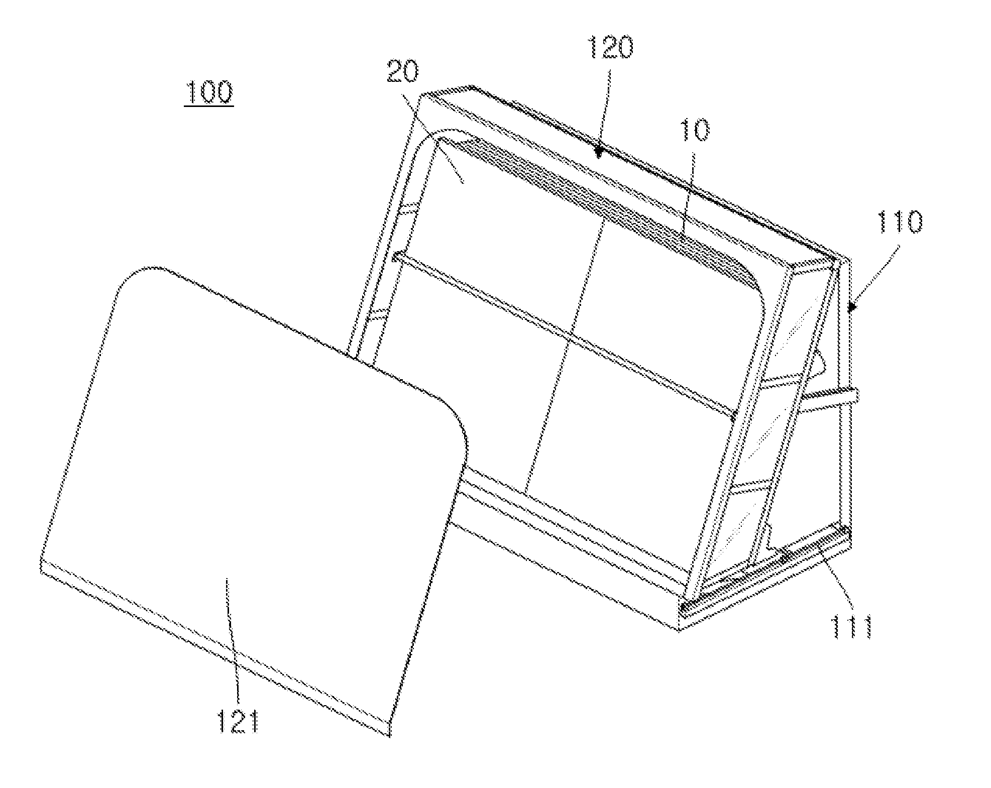
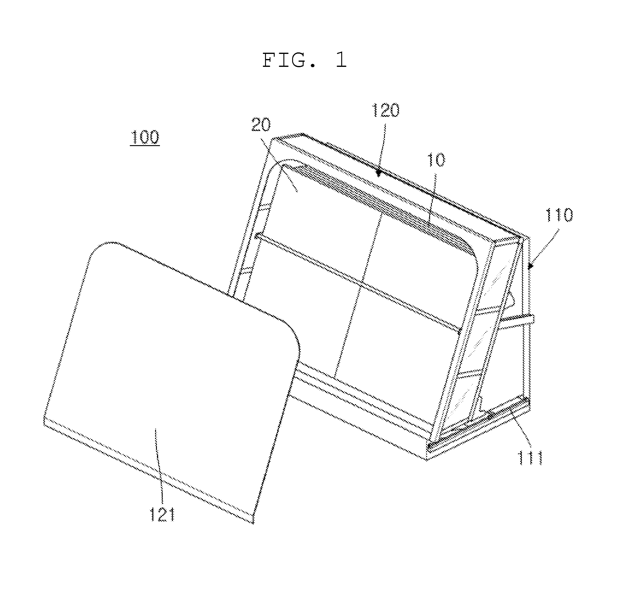
[0024]FIG. 1 is a perspective view showing a glass substrate packing container according to the present invention. As shown in FIG. 1, the glass substrate packing container 100 shown in FIG. 1 is used for packing a plurality of glass substrates 10 which are used for manufacturing a display panel, such as a liquid crystal display (LCD), a plasma display panel (PDP), an organic light-emitting diode (OLED) or a touch screen panel (TSP).

[0025]The glass substrate packing container 100 shown in FIG. 1 includes a loading part 110 and a cover part 120.

[0026]The loading part 110 is a component which forms a basic structure of the packing container 100, and supports the bottom and the rear surface of the glass substrates 10 such that the glass substrates 10 are loaded thereon. (In this specification, the direction from the front to the rear, the direction from bottom to top, and the direction from the left to the right are relative directions that are set for the sake of ease of explanation.)...

second embodiment

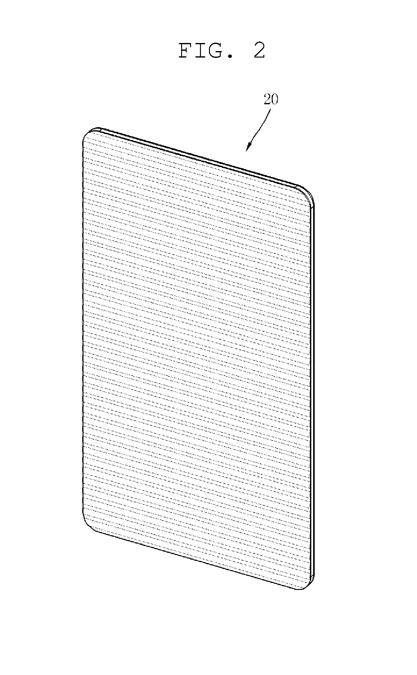
[0029]FIG. 2 is a perspective view showing a glass substrate protective pad 20 according to the present invention, FIG. 3 is an exploded perspective view of the glass substrate protective pad 20 shown in FIG. 2, FIG. 4 is an enlarged side elevation view of a corner of the glass substrate protective pad shown in FIG. 2, and FIG. 5 is an enlarged perspective view of the corner of the glass substrate protective pad shown in FIG. 2.

[0030]The rear surface of the glass substrate protective pad 20, as shown in FIG. 2, is in close contact with a stack of glass substrates. The glass substrate protective pad 20 acts to protect the stack of glass substrates. The glass substrate protective pad 20 is configured as multiple layers. According to this embodiment shown in FIG. 2, the glass substrate protective pad 20 includes a front layer 26, an insert 25, an inner layer 23, an elastic member 24, an insert 22 and a rear layer 21. However, it is apparent that the configuration of the glass substrate...


PUM

PropertyMeasurementUnit
widthaaaaaaaaaa
strengthaaaaaaaaaa
elasticityaaaaaaaaaa

Abstract

A glass substrate protective pad which protects a glass substrate in close contact with the glass substrate. The glass substrate protective pad has multiple layers, the rear layer of the multiple layers which is to be in close contact with the glass substrate containing foamed polymer. A glass substrate packing container for packing a plurality of glass substrates loaded therein, in which the above-described glass substrate protective pad is in close contact with the front surface of the plurality of glass substrates.

Description

CROSS REFERENCE TO RELATED APPLICATION[0001]The present application claims priority from Korean Patent Application Number 10-2013-0040952 filed on Apr. 15, 2013, the entire contents of which are incorporated herein for all purposes by this reference.BACKGROUND OF THE INVENTION[0002]1. Field of the Invention[0003]The present invention relates to a glass substrate protective pad and a glass substrate packing container, and more particularly, to a glass substrate protective pad and a glass substrate packing container which can significantly reduce the breakage rate of a glass substrate.[0004]2. Description of Related Art[0005]A packing container is used as a means for packing a plurality of glass substrates which are used for a display panel or the like. For instance, a glass substrate manufacturer packs a plurality of glass substrates that are manufactured in a packing container before delivering the glass substrates to a display panel manufacturer. The glass substrate packing contain...

Claims


Application Information

Patent Timeline
Patent Type & Authority Applications(United States)
IPC IPC(8): B32B5/18B32B3/26B32B7/02B32B3/30B32B7/022
CPCB32B5/18B32B7/02B32B3/266B32B3/30B32B27/065B32B2266/0221B32B2266/025B32B2571/00Y10T428/24331Y10T428/1376Y10T428/24504Y10T428/24983Y10T428/249981Y10T428/249953B32B7/022B65D85/48B65D65/44B32B27/08B65D81/02B65D81/127B65D81/107B65D81/022
Inventor LEE, BUMROKIM, SEOK-WOONGMOON, SANGKULEE, KYU-HWAN
Owner SAMSUNG CORNING PRECISION MATERIALS CO LTD
Learn More