Denture with suction attachment

Inactive Publication Date: 2008-12-04
DELANEY II PAGE W
View PDF16 Cites 12 Cited by
  • Summary
  • Abstract
  • Description
  • Claims
  • Application Information

AI Technical Summary

Benefits of technology

[0009]A user of the denture with its suction attachment need only position the denture properly in the mouth, attach the suction line from the pump to the valve of the denture, and draw a partial vacuum by actuating the suction pump. The check valve automatically seals the partial vacuum within the suction chamber of the denture and use

Problems solved by technology

Temporarily installed artificial tooth structures, e.g., bridgework a

Method used


Image

  • Denture with suction attachment
  • Denture with suction attachment
  • Denture with suction attachment

Examples


Example

[0016]Similar reference characters denote corresponding features consistently throughout the attached drawings.

DETAILED DESCRIPTION OF THE PREFERRED EMBODIMENTS

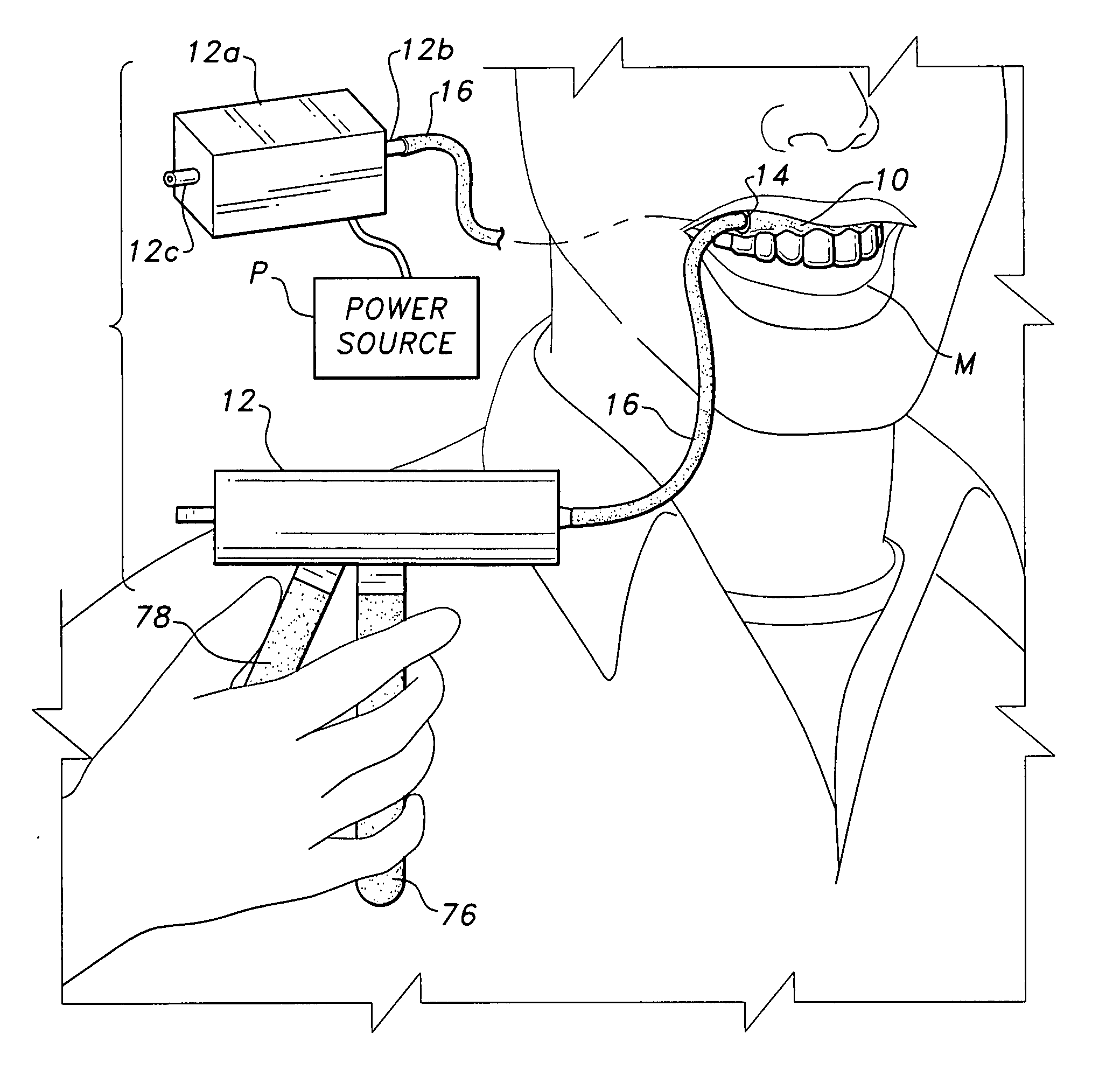
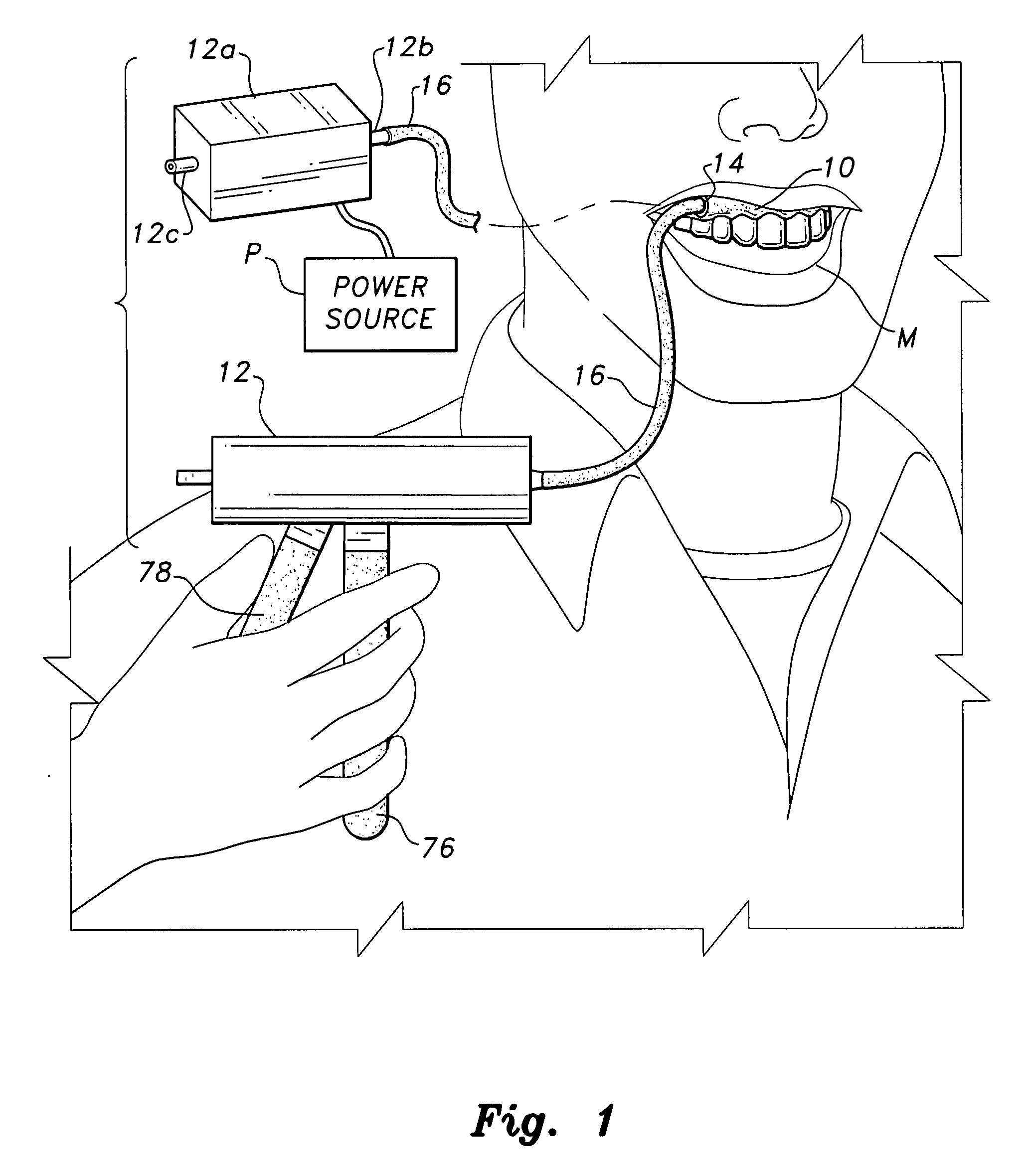
[0017]The present invention relates to a denture, specifically, a dental plate, which is removably secured within the mouth of the user by suction. The denture includes various valve mechanisms and a separate, externally disposed manually or electrically actuated suction pump, which is removably connected to the denture to produce and apply the suction required to secure the denture in the mouth of the user.

[0018]FIG. 1 of the drawings provides an environmental perspective view of an exemplary denture, e.g., upper plate 10, in the process of being secured in the mouth M of the user or wearer. The user is manipulating an external, handheld suction pump 12, which is removably connected to a suction check valve 14 in the dental plate 10 by a suction tube or line 16. The suction tube or line is preferably rigid or semi-rigid, but...


PUM


Abstract

The denture with suction attachment is an upper or lower denture plate having a floor with at least one suction cavity formed therein, at least one check valve for sealing the chamber formed by the suction cavity and the user's mouth when the denture is installed therein, and at least one suction passage extending between the valve and one suction cavity. The suction cavity may have one or more cavities extending generally across the span of an upper plate, or along the gum line of a lower plate. The suction cavity or cavities are preferably provided with a peripheral seal of a soft, resilient silicone material, or other suitable seal. A suction pump is also provided for removable attachment to the check valve. A magnetic attachment is preferably provided for securing the end of the interconnecting suction pump line to the check valve of the denture.

Description

BACKGROUND OF THE INVENTION[0001]1. Field of the Invention[0002]The present invention relates generally to dental appliances. More specifically, the present invention relates to a denture with suction attachment so that the denture is held in place in the mouth of the user by applying suction through a check valve to reduce air pressure within a suction cavity within the denture.[0003]2. Description of the Related Art[0004]Temporarily installed artificial tooth structures, e.g., bridgework and denture plates, have been known for a considerable period of time. Such dentures are conventionally held in place in the mouth by mechanical means, e.g., a closely fitting structure that secures to other natural teeth in the mouth, or by adhesive means, e.g., denture cream. In situations where complete denture plates are used, an adhesive has been conventionally used for attachment in the mouth, as no natural tooth structure remains for mechanically attaching the denture structure in the mouth...

Claims


Application Information

Patent Timeline
IPC IPC(8): A61C13/24
CPCA61C13/245A61C13/25
Inventor DELANEY, II, PAGE W.
Owner DELANEY II PAGE W
Why Eureka
Try Eureka