

A Crankcase Scavenged Two-Stroke Internal Combustion Engine Having an Additional Air Supply
- Summary
- Abstract
- Description
- Claims
- Application Information
AI Technical Summary
Benefits of technology
Problems solved by technology
Method used
Image

Examples
first embodiment
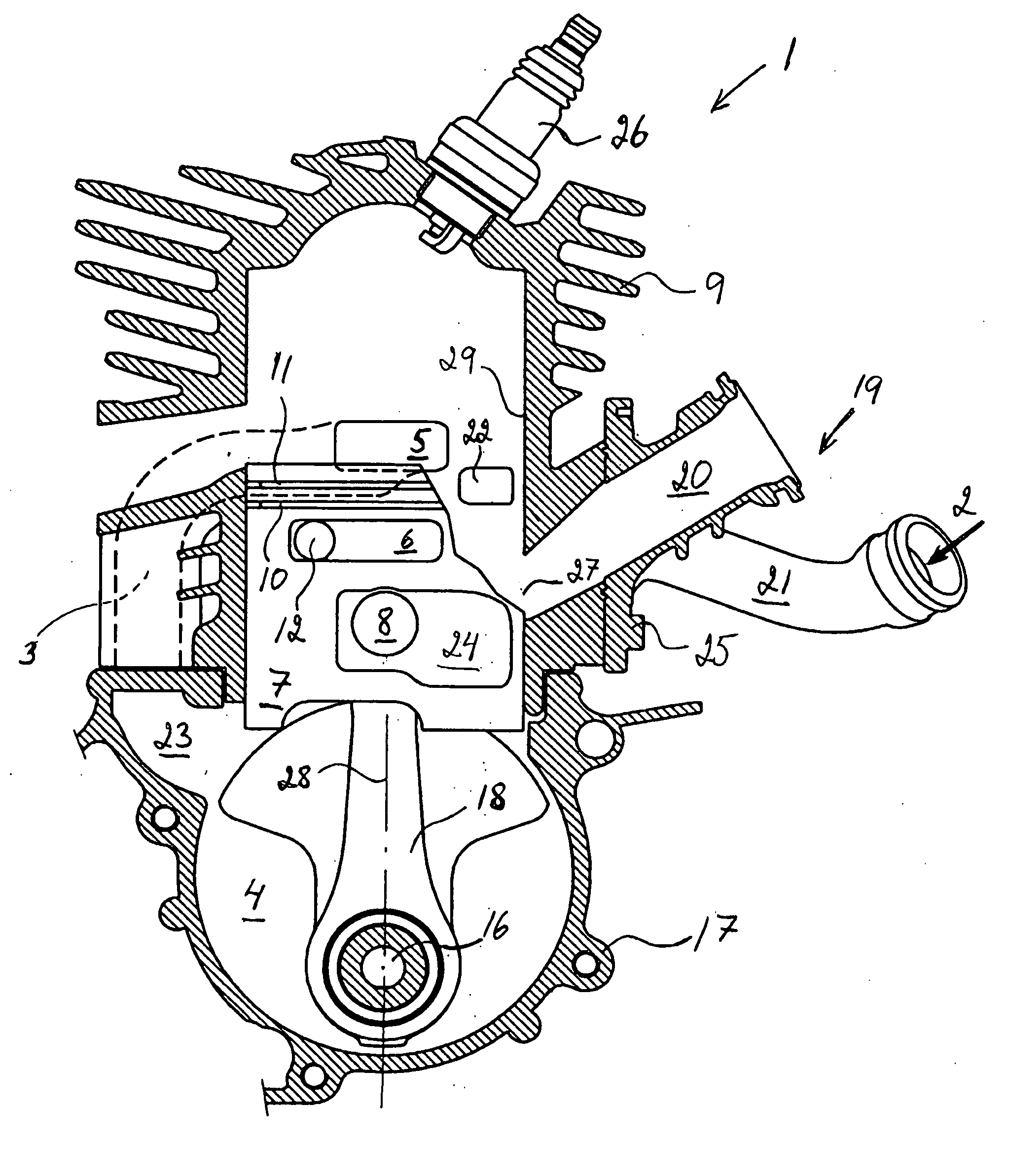
[0010]With reference to FIG. 1 an engine according to the invention is shown. For clarity reasons the cylinder 9 and crankcase 17 is shown in a longitudinal cross-section, but the piston 7 is shown in a side view. This makes it easier to see a number of recesses in the piston. Also the piston is partially cut away to make all ports in the cylinder wall visible. This engine has two transfer ducts 3, but only one is visible, but could also have three, four or five or possibly one. This means that the recesses shown in the piston cooperate with ports above the plane of the paper while recesses on the not visible backside of the piston cooperate with the shown ports. The engine 1 has a cylinder 9 with cylinder bore having a cylinder wall 29. A piston 7 is intended to be movable in the cylinder bore. The piston is connected to a crankshaft 16 via a piston rod 18. The cylinder is attached to a crankcase 17. The underside of the piston 7 and the crankcase 17 forms a crankcase volume 4 that...
second embodiment
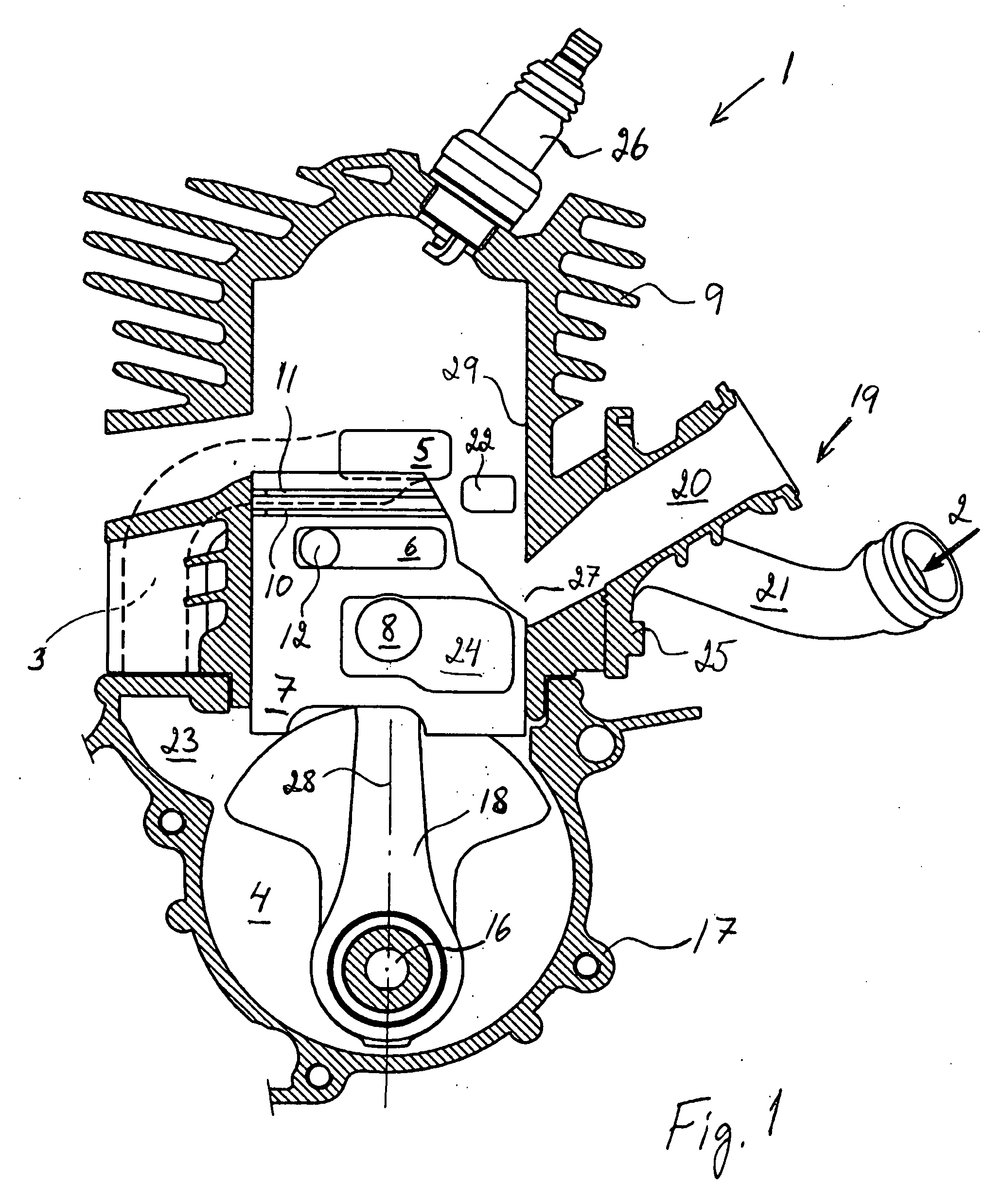
[0015]FIG. 2 shows the invention. Here the flow channel 13 is arranged as an essentially longitudinal duct in the cylinder wall 14, which has at least an open end 15 located essentially laterally beside a transfer port 5. This means that the first recess 6 will register with both the open end 15 and the transfer port 5 for certain first piston positions. The flow channel 13 opens up in the crankcase volume below the piston in the cylinder wall or in the crankcase 17. This means that it communicates the transfer port with the crankcase volume. Usually the flow channel 13 is arranged to be open towards the cylinder wall in its entire length. Its length is greater than the height of the piston so that the flow channel 13 opens up for the flow below the piston. Usually this open flow channel 13 is formed by die-casting of a cylinder 9 and the flow channel has a shape of an open groove 13.
[0016]Both embodiments show an engine wherein the additional air supply 2 to the transfer ducts is a...
third embodiment
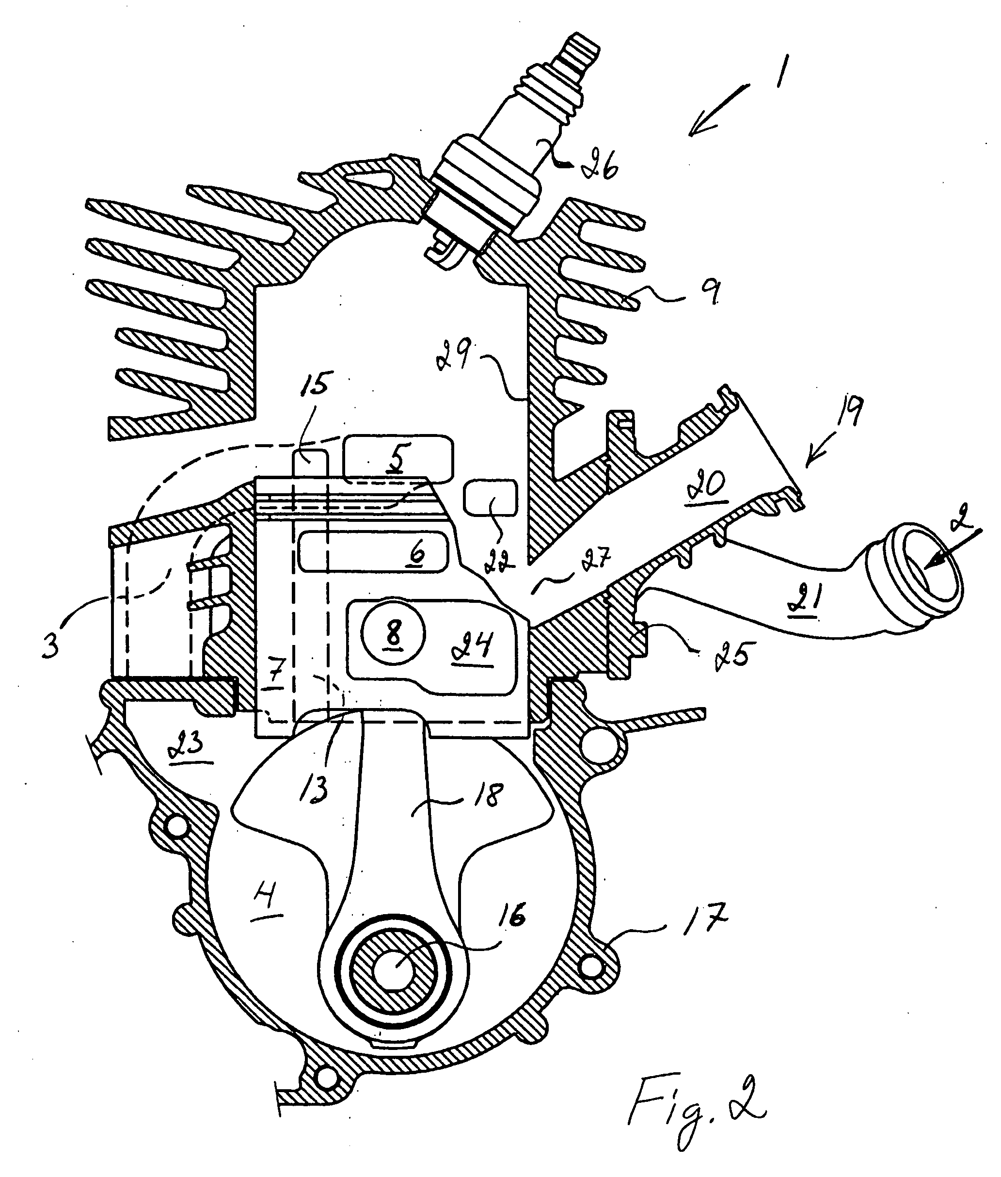
[0017]The two shown embodiments are thus so called piston-ported engines considering the supply of additional air. This also applies to the third embodiment shown in FIG. 3. However the invention could also be used for engines having its additional air supplied directly to its transfer ducts 3 through check valves, also called Reed valves. Also in this case the feed of air would be improved by the invention giving an improved condition at different speeds for feeding of the additional air.
[0018]FIG. 3 shows an engine wherein the flow channel 14 is arranged in the cylinder wall 29 between an air supply port 22 and an intake port 27 at the surface of the cylinder bore. The flow channel 14 could also be arranged deeper down in the cylinder wall and / or in a connected intake system 19. Especially simple would be to arrange the flow channel as a depression in either or both of the meeting mounting planes between the cylinder and the intake system 19. All these options create a communicati...
PUM
 Abstract
Description
Claims
Application Information