
Aircraft with an air intake for an air breathing propulsion engine

Active Publication Date: 2016-03-17
AIRBUS HELICOPTERS DEUT GMBH
View PDF29 Cites 22 Cited by
  • Summary
  • Abstract
  • Description
  • Claims
  • Application Information

AI Technical Summary

Benefits of technology

The present invention provides an aircraft with air intakes that have reduced engine installation losses and are protected against potentially damaging influences. The air intakes have the ability to control the mass-flow entering them, which reduces the risk of hot gas re-ingestion. The aircraft also has a simple and efficient bypass system for incoming air. This results in a longer maintenance and cleaning interval, which is beneficial for the aircraft's overall performance and safety.

Problems solved by technology

As these hot gases may have temperatures between 500° C. and 700° C., this may not only lead to massive performance drops of the engine, but also lead to major problems in operational flight and certification of the entire helicopter.
Another problem that occurs with static intakes compared to dynamic intakes is that a static intake ingests all available surrounding air in all kind of flight conditions.
While this is advantageous e.g. in hover, it is disadvantageous e.g. in fast forward flight conditions.
Furthermore, in slow to medium forward flight conditions and, thus, slow to medium air flow conditions, the downwash of a helicopter's main rotor interacts with the static intake, leading to a variation of mass-flow entering the static intake, as an upper part of the static intake that is oriented towards the main rotor may ingest more mass-flow than its lower part.
In general, this leads to increased engine installation losses due to additional swirl in the engine plenum.
However, because of these conventional air-permeable engine protections dynamic pressure is not increased sufficiently in the corresponding static intakes, which therefore generally lack in their performance during fast forward flight conditions.

Method used


Image

  • Aircraft with an air intake for an air breathing propulsion engine
  • Aircraft with an air intake for an air breathing propulsion engine
  • Aircraft with an air intake for an air breathing propulsion engine

Examples


Embodiment Construction

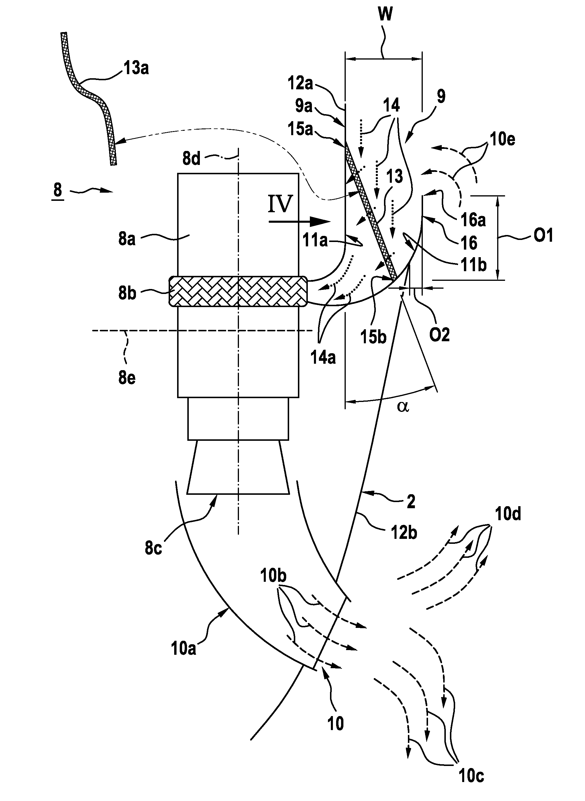
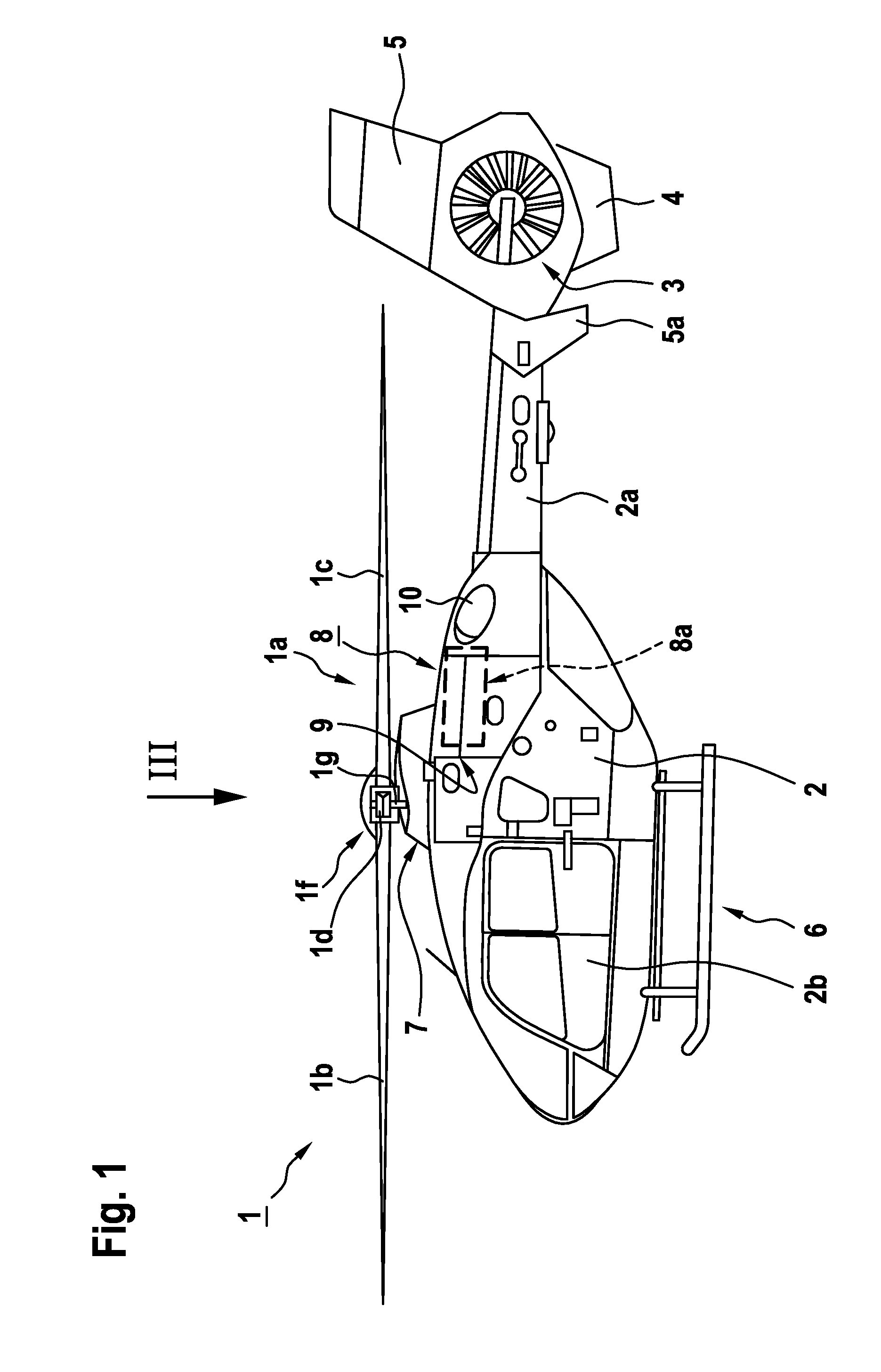
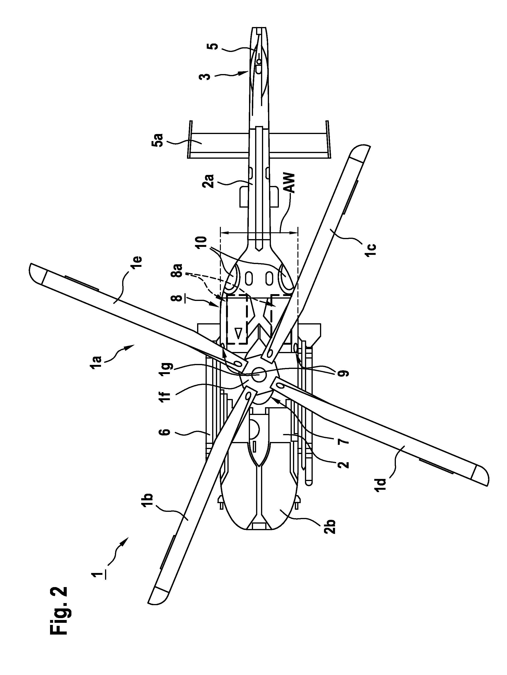
[0069]FIG. 1 shows an aircraft 1 with a fuselage 2. According to one aspect, the aircraft 1 is equipped with a power generation system 8. Preferably, this power generation system 8 comprises at least one air breathing propulsion engine 8a with an associated gas exhaust 10. The at least one air breathing propulsion engine 8a is preferably supplied with an intake air stream (14 in FIG. 13) by means of at least one associated dynamic air intake 9. This at least one dynamic air intake 9 is illustratively provided in a region of a main gear box 7 of the helicopter 1, and in particular slightly downstream of said main gear box 7, but may alternatively also be positioned in an application-specific manner at other locations on the fuselage 2.

[0070]By way of example, the aircraft 1 is illustrated as a rotary-wing aircraft and, more particularly, as a helicopter. Thus, for purposes of simplicity and clarity, the aircraft 1 is hereinafter also referred to as the “helicopter 1”. It should, howe...


PUM


Abstract

An aircraft with a fuselage that accommodates at least one air breathing propulsion engine, the fuselage having a maximum fuselage width determined in the region of the at least one air breathing propulsion engine and comprising at least one front fuselage cowling and at least one rear fuselage cowling that are each covering the at least one air breathing propulsion engine at least partly, the at least one front and rear fuselage cowlings being spaced apart from each other in a direction transverse to a longitudinal axis of the at least one air breathing propulsion engine by a predetermined cowling offset to define a dynamic air intake through which an intake air stream is supplied to the at least one air breathing propulsion engine in operation.

Description

CROSS REFERENCE TO RELATED APPLICATION[0001]This application claims priority to European patent application No. 14 400046.0 filed on Sep. 12, 2014, the disclosure of which is incorporated in its entirety by reference herein.BACKGROUND OF THE INVENTION[0002](1) Field of the Invention[0003]The invention is related to an aircraft with a fuselage that accommodates at least one air breathing propulsion engine, said fuselage being provided with an air intake through which an intake air stream is supplied to said at least one air breathing propulsion engine in operation, said aircraft comprising the features of claim 1.[0004](2) Description of Related Art[0005]In aircrafts with air breathing propulsion engines, such as gas turbine engines, gas propelled engines or diesel engines, a sufficient air supply to the air breathing propulsion engines must be ensured such that these engines are able to combust a provided air / fuel mixture properly in order to deliver a required amount of power to an...

Claims


Application Information

Patent Timeline
IPC IPC(8): B64D33/02F02M35/04F02M35/10F02M35/16
CPCB64D33/02F02M35/16F02M35/048F02M35/10111B64C27/04B64D2033/022F02C7/052F02C7/055F05D2260/607F05D2220/329F02C7/05B64D2033/0253Y02T50/60
Inventor MORES, SEBASTIANLOSER, FRANKPROBST, STEFANMATT, MICHAEL
Owner AIRBUS HELICOPTERS DEUT GMBH
Learn More