
Fallopian tube occlusion device

Active Publication Date: 2008-12-11
REX MEDICAL LP
View PDF35 Cites 50 Cited by
  • Summary
  • Abstract
  • Description
  • Claims
  • Application Information

AI Technical Summary

Benefits of technology

[0014]In one embodiment, the retention member has a plurality of shape memory struts and the step of exposing the retention member enables the struts to move toward a shape memorized position.

Problems solved by technology

In other techniques, radiofrequency energy electrodes are inserted and energized to thermally damage the tube, causing scarring to occlude it.

Method used


Image

  • Fallopian tube occlusion device
  • Fallopian tube occlusion device
  • Fallopian tube occlusion device

Examples


Embodiment Construction

[0032]Referring now in detail to the drawings where like reference numerals identify similar or like components throughout, the several views, an occlusion device for placement in the fallopian tubes for contraception is disclosed. The device can be inserted minimally invasively and preferably in an office procedure. A hysteroscope can be used for direct visualization. The occlusion device includes a securement member and mesh material. The securement member provides for attachment to the fallopian tube as well as a support or retention for the various embodiments of the mesh described below.

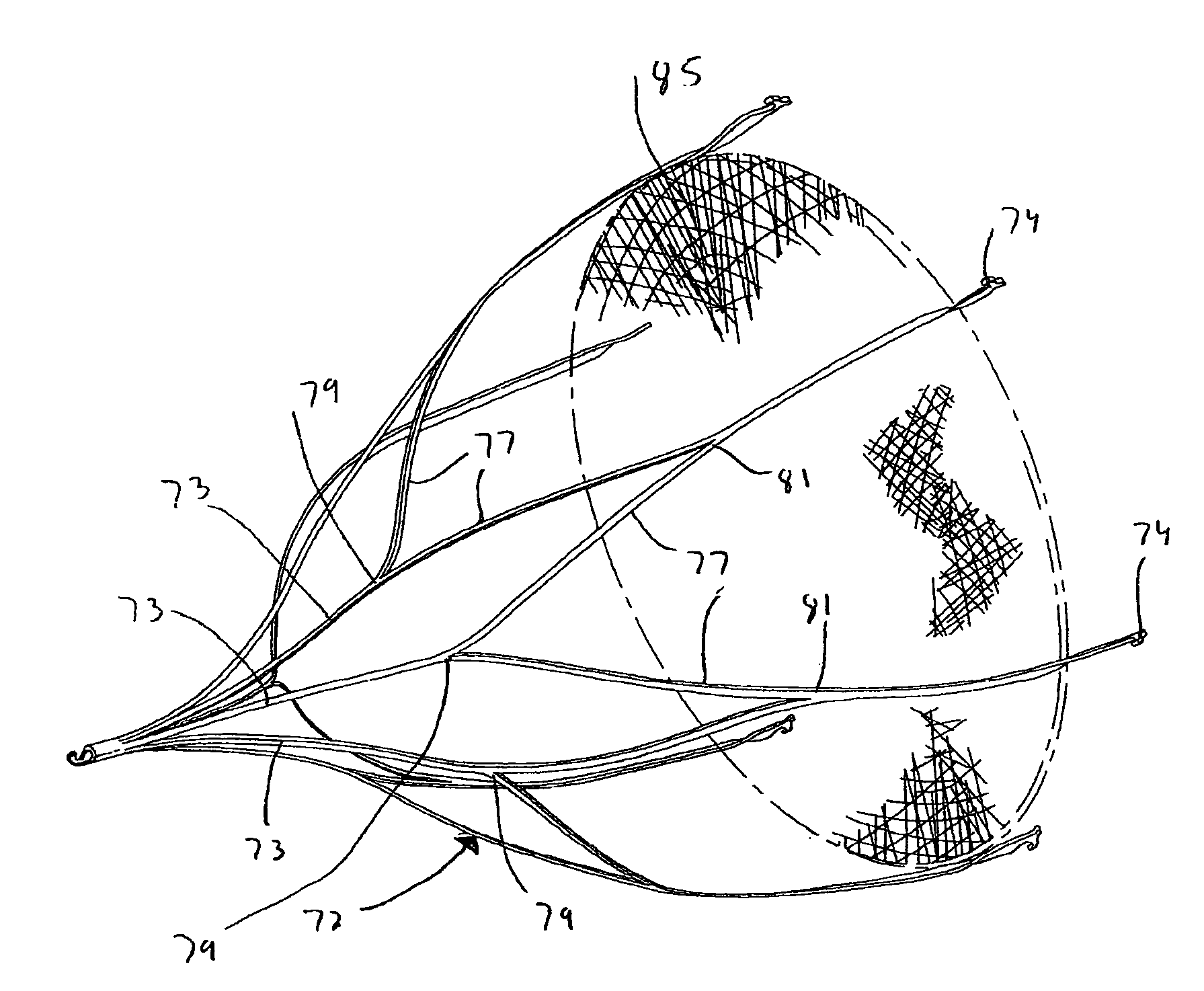
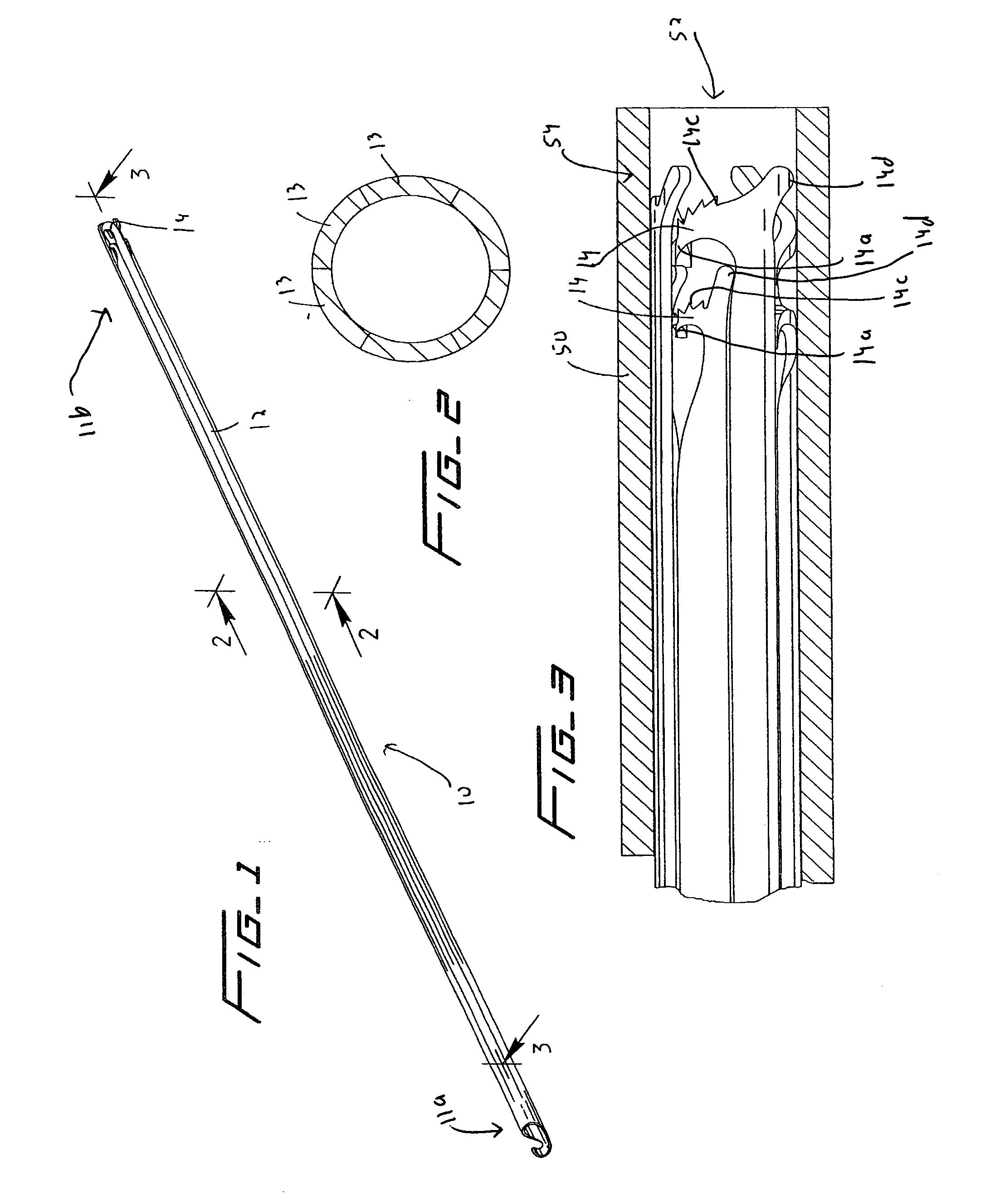
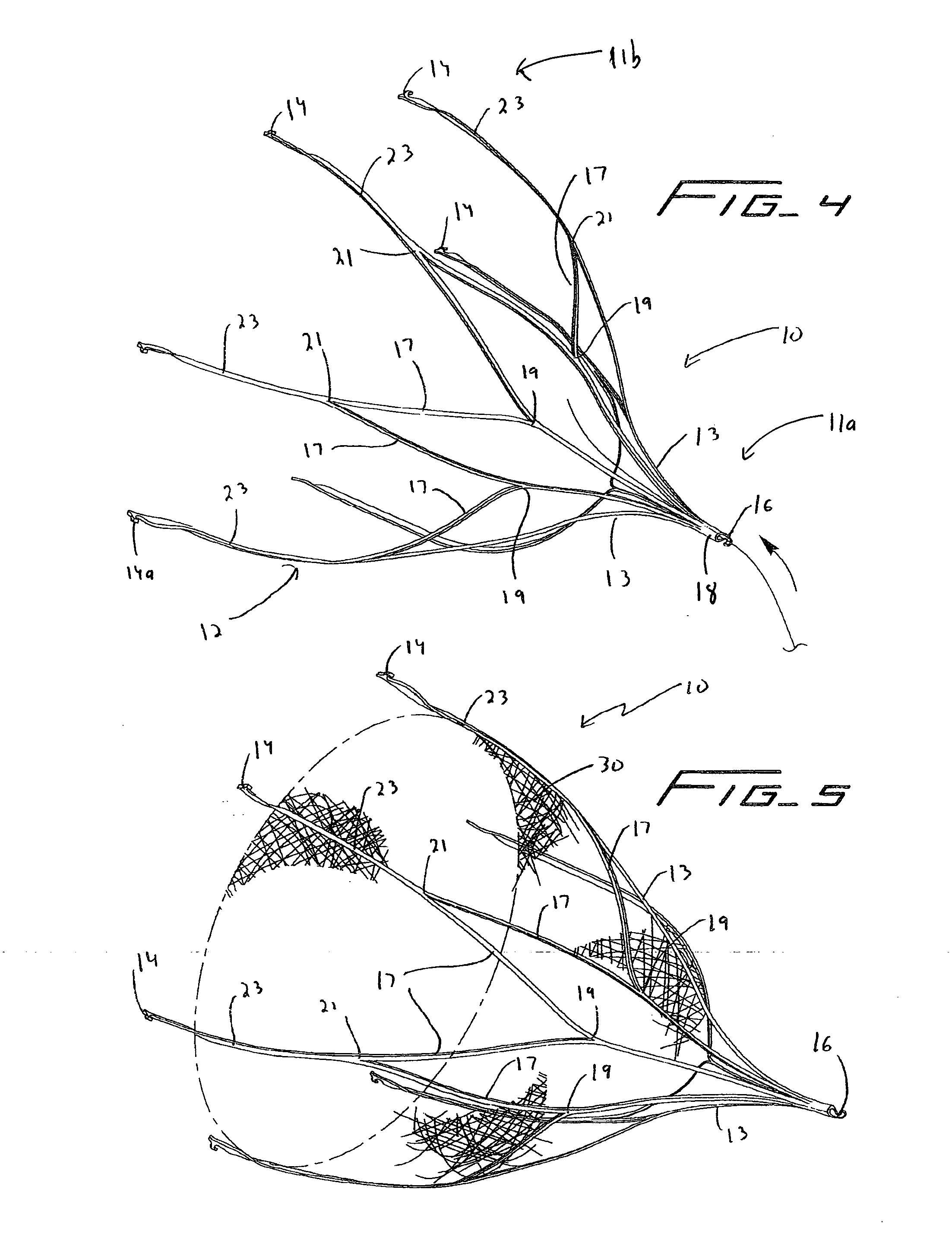
[0033]With initial reference to FIGS. 1-3 which shows the occlusion device 10 in the low profile collapsed delivery configuration, and FIG. 4, which shows the occlusion device 10 in the expanded placement configuration, the occlusion device 10 includes a securement or retention component (member) 12. Securement member 12 has engagement hooks 14 for engaging the fallopian tube wall to retain the ...


PUM


Abstract

A device for occluding the fallopian tube comprising a retention member and a mesh material supported by the retention member. The retention member has a first lower profile configuration for delivery and a second expanded configuration for placement within the fallopian tube. The mesh material is configured to block passage of an egg through the tube. The member has a plurality of tube engagement members to secure the retention member to the fallopian tube.

Description

[0001]This application claims priority from provisional application Ser. No. 60 / 932,405 filed May 31, 2007, the entire contents of which is incorporated herein by reference.BACKGROUND[0002]1. Field of the Invention[0003]This application relates to a minimally invasive device for occluding the fallopian tubes.[0004]2. Background of Related Art[0005]Tubal ligation is one method of female sterilization. It can be performed laparascopically by access through the patient's abdomen where the surgeon severs and closes the ends of the fallopian tubes by tying, applying clamps or cauterization. These devices achieve occlusion by external application to the tube.[0006]Other methods involve transcervical access. In some techniques, various agents are injected within each of the fallopian tubes to close or block the tubes. In other transcervical procedures, mechanical devices are inserted and anchored within the tube to promote tissue ingrowth and scar tissue formation to occlude the tubes. In ...

Claims


Application Information

Patent Timeline
IPC IPC(8): A61F6/06
CPCA61F6/225
Inventor MCGUCKIN, JR., JAMES F.SCHALLER, DAVID M.BRESSLER, JAMES ERICH
Owner REX MEDICAL LP
Learn More