Sealing Band

Inactive Publication Date: 2008-12-11
ISO CHEM GMBH
View PDF1 Cites 8 Cited by
  • Summary
  • Abstract
  • Description
  • Claims
  • Application Information

AI Technical Summary

Benefits of technology

[0008]As a result of this design, all types of foam can be impregnated with relatively little effort. Thus, for example, relatively closed-cell foams can be impregnated more easily and more homogeneously; open-cell foams can even be saturated with high-viscosity impregnates; and even completely closed-cell foams can be provided with an impregnate in the area of the notches or recesses by surface adhesion, as a result of which the desired properties attributable to the impregnate such as delayed recovery can be achieved.
[0009]The notches or recesses in the foam are preferably arranged in such a way that they have little or no negative effect on the sealing action in the functional direction of the joint-sealing tape. Thus the inventive joint-sealing tape does not suffer from any disadvantages at all versus the conventional joint-sealing tape in this respect either.
[0010]According to the invention, the dimension of the notches or recesses in the longitudinal direction of the joint-sealing tape is at least as long as the dimension of the notches or recesses in the transverse direction of the joint-sealing

Problems solved by technology

Such impregnates also lead to a delayed recovery of the foam after its compression, because the impregnates usually contain adhesive substances, which settle on the cell webs of the foam structure and adhere there.
Nevertheless, the complete saturation of relatively closed-cell foams is very

Method used


Image

  • Sealing Band
  • Sealing Band
  • Sealing Band

Examples


Example

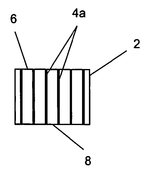
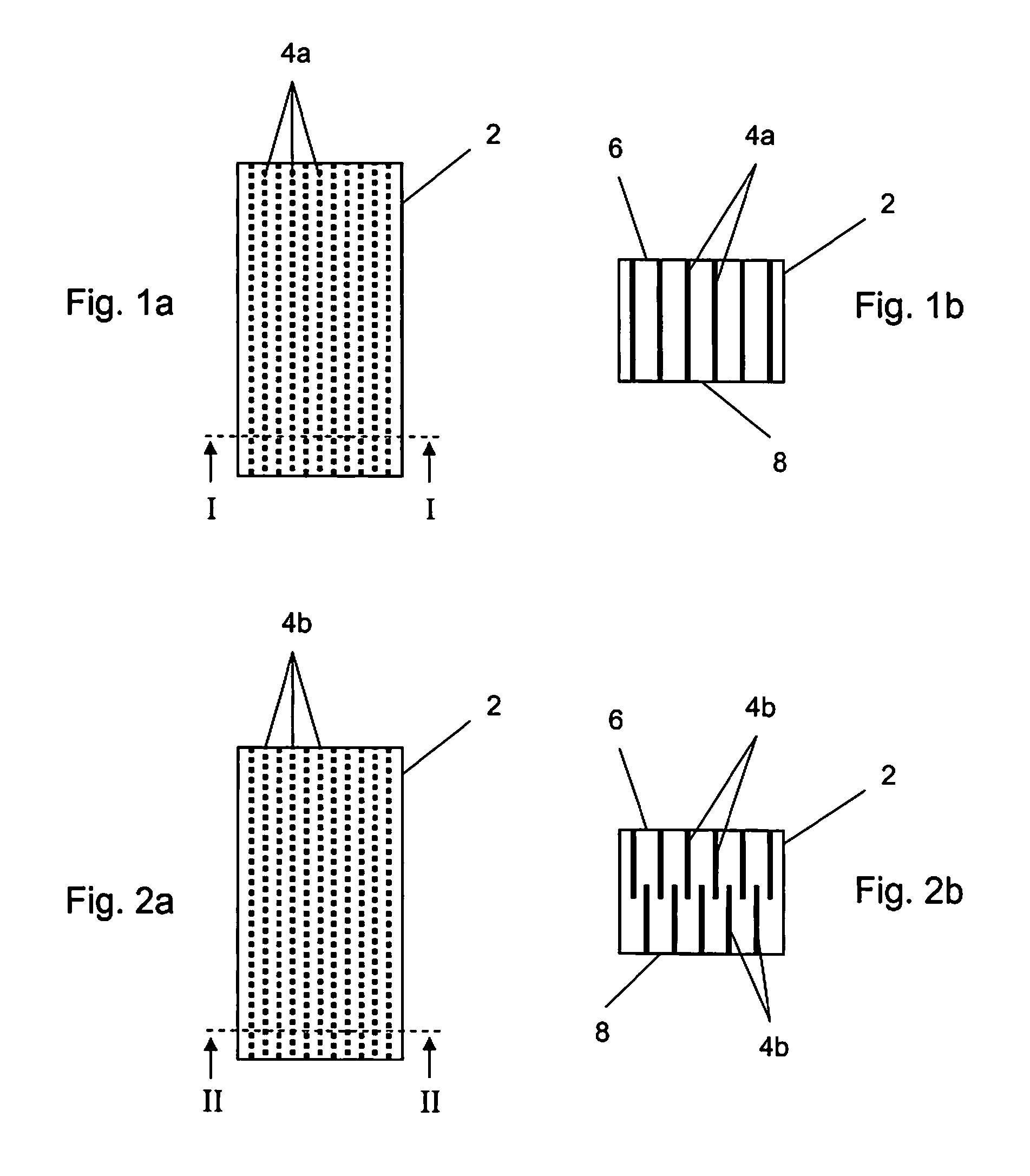
[0026]FIG. 1a shows a top view of a first embodiment of an inventive joint-sealing tape. The joint-sealing tape consists of flexible foam 2, which can be formed out of a relatively open-cell foam material with high air permeability. Preferably, however, it is a relatively closed-cell foam material with low permeability and small pore cross sections. Foams with air permeability values which are between the two extremes just mentioned above can also be used within the scope of the present invention. Preferred foam materials are polyurethane and polyethylene foams which are able to recover their original state completely or almost completely after having been compressed. The dimensions of the joint-sealing tape are not shown to scale in FIG. 1a, because a joint-sealing tape usually extends much farther in the longitudinal direction and is therefore wound up into a roll. The inventive joint-sealing tape shown in FIG. 1a therefore represents merely a section of the overall length of the ...

Example

[0029]The second embodiment shown in FIGS. 2a and 2b differs from the first embodiment in that the upper notches 4b, which extend into the foam 2 from the top surface 6 of the foam strip, extend only about half-way through the thickness of the foam 2, whereas identical notches 4b, offset from the first set of notches, extend about half-way through the thickness from the bottom surface 8 of the foam 2. As a result, the notches do not have to penetrate as deeply into the foam 2, but it is still ensured that the foam 2 will be completely saturated.

Example

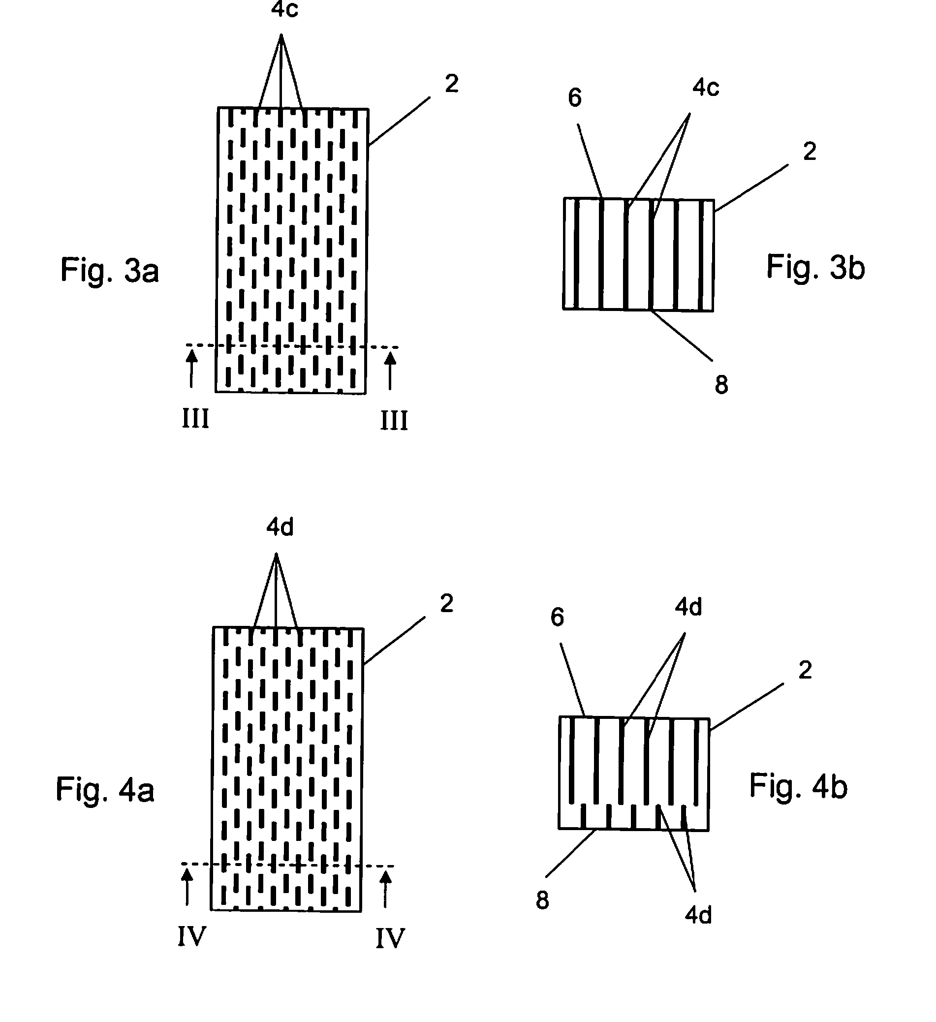
[0030]An especially advantageous third embodiment of the joint-sealing tape is shown in FIGS. 3a and 3b. The difference from the embodiment of FIGS. 1a and 1b is that the notches 4c are lengthened in the longitudinal direction of the joint-sealing tape and thus form strip-like, longitudinal notches. As a result, the perforated component of the foam 2 is increased in the longitudinal direction, and superior saturation of the foam 2 with the impregnate is achieved. The length of the individual strip-like longitudinal notches will usually be in the range of a few millimeters, but almost any length can be selected. The value chosen will depend on, among other things, the dimensions of the foam.


PUM


Abstract

The joint-sealing tape of flexible foam material (2) capable of recovery after compression is saturated with an impregnate and provided with a plurality of notches or recesses (4a, 4b, 4c, 4d), which serve to accept and to distribute the impregnate in the foam (2).

Description

CROSS REFERENCE TO RELATED APPLICATION[0001]This application claims priority to European patent application EP 07 007 803.5, filed Apr. 17, 2007.FIELD OF THE INVENTION[0002]The present invention relates to the field of foam tapes for creating sealing joints against rain, air, wind, and sound and / or to insulate against heat loss, such as in the construction industry.BACKGROUND OF THE INVENTION[0003]These types of joint-sealing tapes usually consist of polyethylene or polyurethane foam, and are used, for example, in the construction industry, where the joints between window frames or door frames and the masonry must be sealed. The foam materials have a cellular structure made up of webs with pores between them. The spectrum of flexible foams extends from closed-cell foams, which allow virtually no air to pass through, to open-cell foams, which have relatively high permeability to air. At least the open-cell foams are usually saturated with an impregnate to achieve the desired sealing ...

Claims


Application Information

Patent Timeline
IPC IPC(8): F16J15/02
CPCE04B1/6812Y10T428/24322Y10T428/24273Y10T428/24496Y10T428/24479Y10T428/249953Y10T428/249976
Inventor DEIB, MARTIN
Owner ISO CHEM GMBH
Why Eureka
Try Eureka