Hygiene washing apparatus
Inactive Publication Date: 2005-11-10
PANASONIC CORP
4 Cites 58 Cited by
AI-Extracted Technical Summary
Problems solved by technology
However, such disinfection work is troublesome to a person.
In the conventional sanitary washing apparatus 902, however, dirt on the human body washing nozzle device 907 is difficult to sufficiently remove by spraying water which is washing water, and a sterilization effect is not also obtained.
Therefore,...
Method used
[0139] Although the flow paths are respectively provided with O-rings 144 as sealing members in order to prevent an internal leak or prevent an external leak, the present invention is not limited to the same. The O-ring may be replaced with a special O-ring such as an X-ring or a V packing in order to reduce a load on a motor.
[0140] Furthermore, in the present embodiment, a reduction gear contained stepping motor which can be positioned with high accuracy even in open control is employed as the motor 141, and its output shaft is mounted on the inner cylinder 142 in such a form that it is inserted thereinto. Although in the first embodiment, the stepping motor is employed as the motor 141, a brush-type general-purpose DC motor or the like can be utilized, provided that even positioning accuracy is ensured. Alternatively, various types of actuators such as a rotary-type solenoid may be used. Although in the first embodiment, the rotary-type flow path switching valve is used, a direct driving flow path switching valve, a flow path switching valve using a diaphragm, or a flow path switching valve for switching a plurality of flow paths by a disk-type inner cylinder, and so on can be also used.
[0146] Thus, the configuration in which the nozzle cleaning switch 309 for transmitting the high-temperature cleaning sterilization mode signal is provided in the main body 200 or the remote control device 300 in the sanitary washing apparatus 100 allows the high-temperature cleaning sterilization to be easily and simply performed only by pressing the nozzle cleaning switch 309.
[0149] Even in the results of experiments on the Escherichia coli, the sterilization effect can be confirmed at 55° C. The higher the temperature is, the larger a high-temperature sterilization action is. However, it is preferable that the upper-limit temperature is 70° C. Thus, the temperature of hot water is set to 55° C. to 70° C., which may not bring about a serious result even if the human body touches the hot water, and allows contamination by fungi and molds to be effectively prevented.
[0151] Furthermore, the flow rate of the hot water passing through the instantaneous heating device 33 is controlled to a predetermined flow rate by the controller 4 at the time of high-temperature cleaning sterilization. That is, the degree of a communication aperture between the washing water inlet 143a and the washing water outlet 143d in the switching valve 14 is taken as a predetermined amount so that the flow rate of the hot water flowing through the instantaneous heating device 33 is controlled by the controller 4. The controller 4 can obtain a flow rate signal from the flow sensor 10. The hot water can be prevented from splashing on the human body by controlling the flow rate of the hot water to a predetermined flow rate. Heat input required for warm water, which is controlled to a predetermined temperature of 40° C., for example, by the heat exchanger 11 to be changed into hot water having a predetermined temperature of 60° C., for example, by the instantaneous heating device 33 is theoretically determined at the flow rate of the hot water. As a result, the flow rate of the hot water passing through the instantaneous heating device 33 is controlled to a predetermined flow rate, thereby eliminating the necessity of providing a temperature sensor in the instantaneous heating device 33. Moreover, an amount of heat required for heating in the sheathed heater 505 can be also reduced by controlling the flow rate of the hot water to a small predetermined flow rate, and the effect of energy saving is obtained together with the above-mentioned safety.
[0154] At the time of high-temperature cleaning sterilization, a plurality of nozzles in each of the posterior nozzle 1 and the bidet nozzle 2 are simultaneously sterilized by high-temperature cleaning with hot water from the nozzle cleaning hole (hot water discharge port) 24d. Even when the posterior nozzle 1 and the bidet nozzle 2 are employed after the high-temperature cleaning sterilization, the posterior nozzle 1 and the bidet nozzle 2 which are sterilization by high-temperature cleaning can be also used. Therefore, the user can wash the private parts at ease in a state where the posterior nozzle 1 and the bidet nozzle 2 are clean by being sterilized.
[0156] On the other hand, portions, on which hot water having a high temperature of 55° C. to 70° C. is exerted, in the posterior nozzle 1 and the bidet nozzle 2 are formed of stainless steel, so that the posterior nozzle 1 and the bidet nozzle 2 sufficiently withstand the high temperature and are highly clean, thereby making it possible to further enhance the effect of high-temperature cleaning sterilization.
[0158] A water stain scale can be prevented from adhering to the posterior nozzle 1 and the bidet nozzle 2 by subjecting the surfaces of the posterior nozzle 1 and the bidet nozzle 2 to water repellent processing. Therefore, the effect of the high-temperature cleaning sterilization can be further enhanced.
[0160] As described in the foregoing, according to the first embodiment, there can be provided a sanitary washing apparatus 100 that can be kept clean easily and simply and can be employed at ease even by a cleanly person by the posterior nozzle 1 and the bidet nozzle 2 for discharging washing water for washing the human body and the nozzle cleaning nozzle 3 for sterilizing the outer surfaces of the spray holes in the posterior nozzle 1 and the bidet nozzle 2 by high-temperature cleaning.
[0215] In the second embodiment, the thermistor 33a, the thermostat 33b, and the temperature fuse 33c differ in reference operating temperatures. Thus, adjustments for preventing overheating in three stages can be made. Further, even if any one of the thermistor 33a, the thermostat 33b, and the temperature fuse 33c fails, the remaining two of them prevent overheating.
[0219] By the functions of the thermistor 33a, the thermostat 33b, and the temperature fuse 33c, overheating of washing water by the sheathed heater 505 and overheating of the sheathed heater 505 itself are prevented.
[0256] On the other hand, when it is judged that the toilet cover is opened, the controller 4 transmits a heating instruction to the instantaneous heating device 33 (step S15). Thus, an amount of heat generated from the sheathed heater 505 is increased.
[0260] On the other hand, when the predetermined time period has elapsed, the controller 4 instructs the instantaneous heating device 33 to raise the heating temperature (step S18). Thus, an amount of heat generated from the sheathed heater 505 is increased.
[0262] As a result, the high-temperature nozzle cleaning vapor is sprayed on the vicinity of the spray hole 25 in the posterior nozzle 1a or the spray hole in the bidet nozzle 2 from the nozzle cleaning nozzle 3. Thus, bacteria or dirt adhering to the vicinity of the spray hole 25 in the posterior nozzle 1a or the spray hole in the bidet nozzle 2 is removed and is sterilized. The nozzle 30 in the second embodiment is formed of resin having high heat resistance which is not deformed even by spraying the nozzle cleaning vapor or the nozzle cleaning hot water.
[0273] In the sanitary washing apparatus 100a according to the present invention, when it is detected by the seating sensor 51, the hole ICs 513a and 513b, and the toilet seat switch 55 that the sanitary washing apparatus 10a has not been employed yet, the cleaning of the posterior nozzle 1a and the bidet nozzle 2 by the nozzle cleaning nozzle 3 is allowed. When the sanitary washing apparatus is employed, therefore, the washing water by the nozzle cleaning nozzle 3 is prevented from adhering to the human body. Thus, the posterior nozzle 1a and the bidet nozzle 2 can be kept clean while giving a sufficient feeling of safety to the user as well as ensuring safety. Further, the posterior nozzle 1 and the bidet nozzle 2 are exposed to high-temperature vapor so that dirt adhering to the posterior nozzle 1a and the bidet nozzle 2 is easily removed, and a sterilization effect is obtained. Further, a sterilization range at high temperatures is enlarged by the diffusion properties of the vapor.
[0274] The posterior nozzle 1a and the bidet nozzle 2 are washed away by the vapor or the heated washing water, and is then cleaned with unheated washing water, so that the temperatures of the posterior nozzle 1 and the bidet nozzle 2 which are sterilized by the vapor or the heated washing water ...
Benefits of technology
[0076] The heat-resistance material may include stainless steel. In this case, at least a part of the human body washing nozzle device is made of stainless steel, so that the sterilization effect by high-temperature cleaning can be further enhanced.
[0077] At least a part of a surface of th...
Abstract
When the human body is washed, washing water is sprayed on a surface to be washed of the human body from a posterior nozzle and a bidet nozzle. On the other hand, when the human body is not washed, the posterior nozzle and the bidet nozzle are subjected to high-temperature cleaning by a nozzle cleaning nozzle. When it is detected that a sanitary washing apparatus has not been employed yet, the posterior nozzle and the bidet nozzle are allowed to be cleaned by the nozzle cleaning nozzle by a controller. After a cleaning operation is terminated, a user is notified that the cleaning operation is terminated by a notification lamp and a speaker. A scale inhibiting material supply device is interposed in a pipe on the upstream side of an instantaneous heating device by the nozzle cleaning nozzle.
Application Domain
BathsDouches +1
Technology Topic
HygieneLoudspeaker +3
Image
Examples
- Experimental program(8)
Example
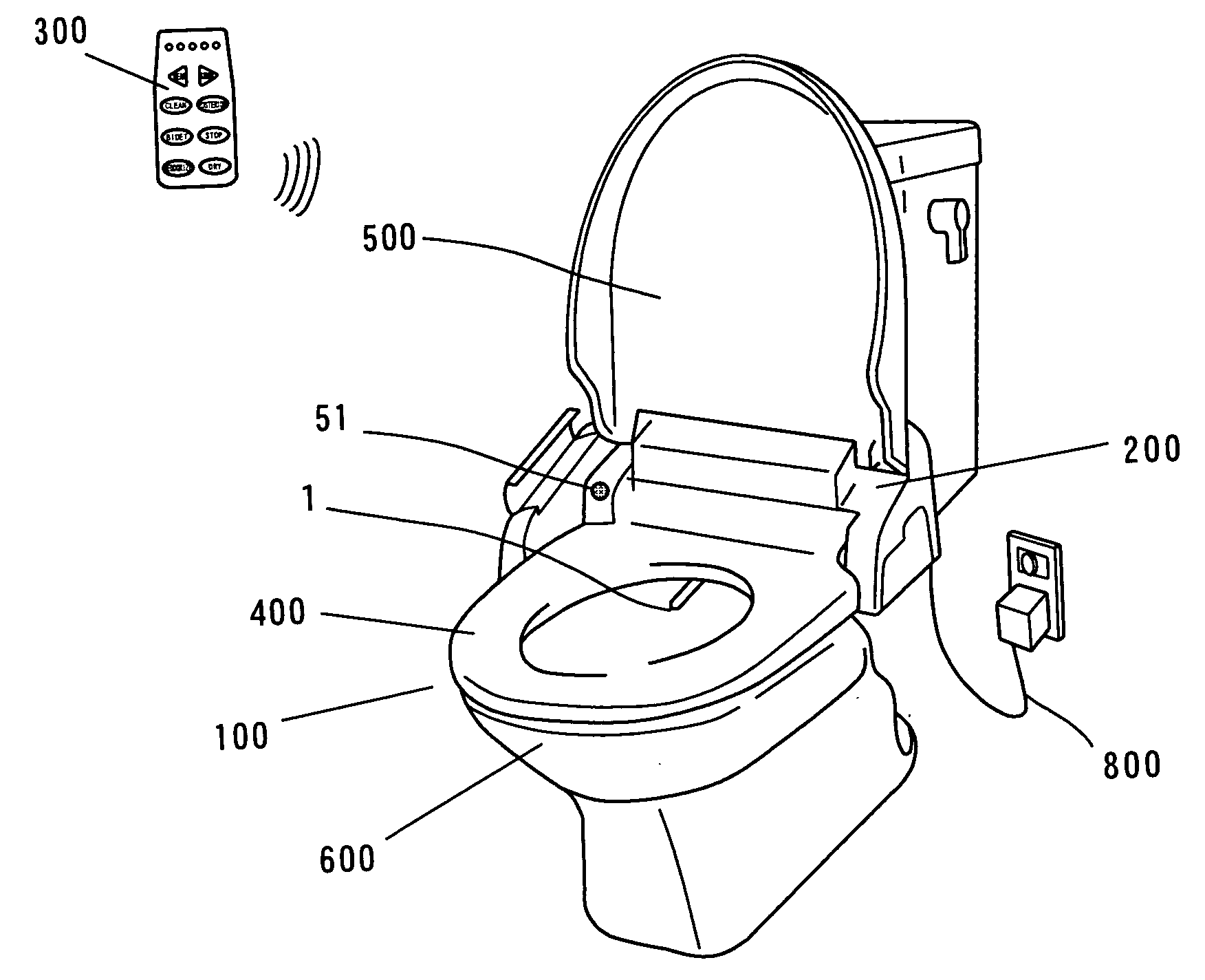
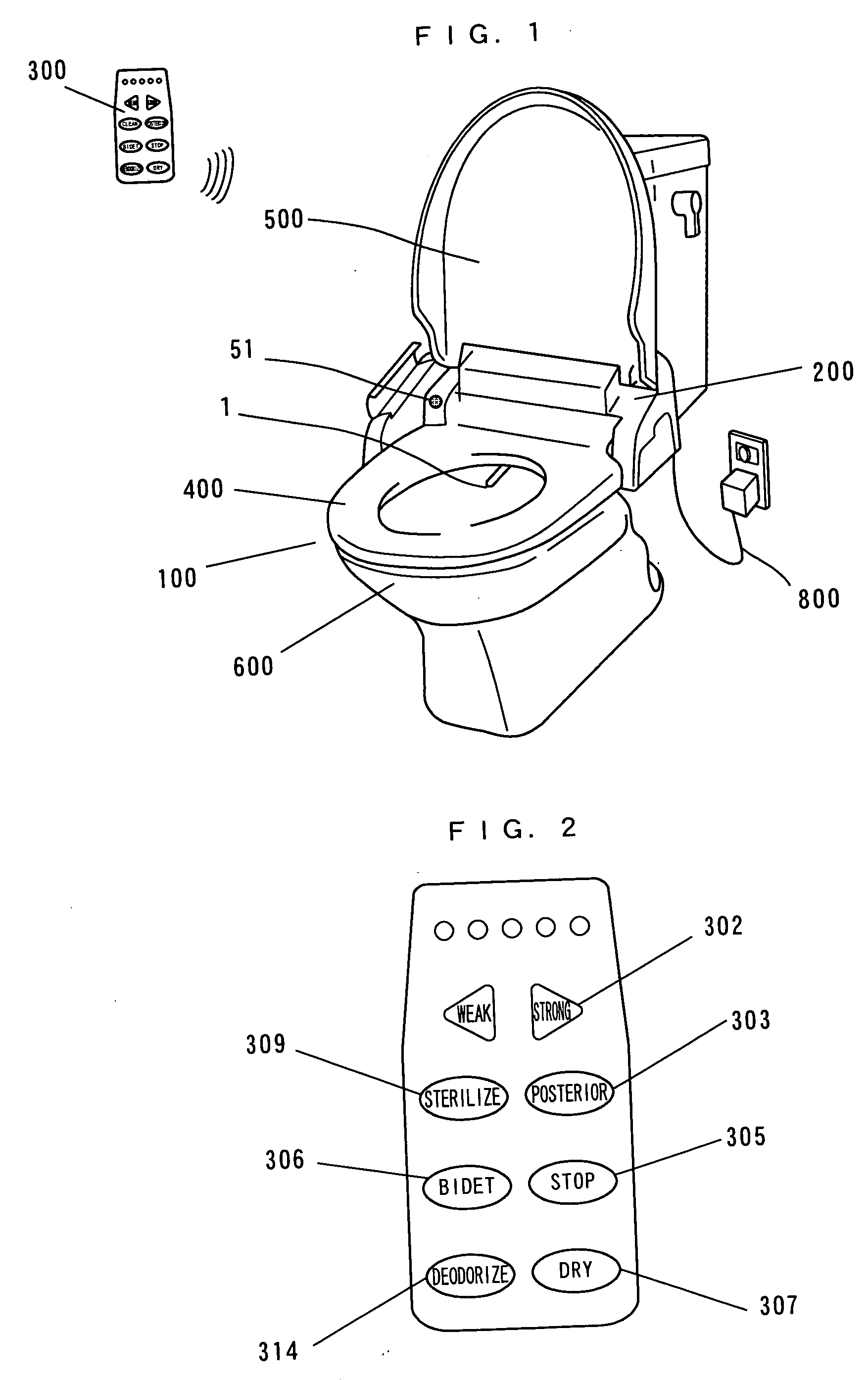
[0115]FIG. 1 illustrates the appearance of a sanitary washing apparatus according to a first embodiment of the present invention.
[0116] In FIG. 1, a hot-water washing toilet seat serving as a sanitary washing apparatus (hereinafter referred to as a sanitary washing apparatus) 100 is installed on a toilet bowl 600. The sanitary washing apparatus 100 comprises a main body 200, a cover (toilet cover) 500, a toilet seat 400 on which a user is to sit, and so on. The sanitary washing apparatus 100 comprises a water supply pipe for receiving the supply of washing water from a tap water (indicated by a tap water pipe 201 shown in FIG. 3) and an electrical cable 800 for receiving the supply of power from an outlet on a wall surface. The inside of the sanitary washing apparatus 100 comprises a posterior washing function for washing the anus of a user, a bidet washing function for washing the female private parts after urination, a drying function for drying the private parts of the human body after washing, a room heating function for heating a toilet space at cold times, and so on. The functions are respectively exerted by a user pressing various types of switches in a remote control device (a remote controller) 300 mounted on the wall surface. A seating sensor 51 serving as a detector for detecting the presence of a user is provided in the toilet seat 400. In the present embodiment, the seating sensor 51 detects the presence or absence of seating of a user on the toilet seat 400 using infrared rays.
[0117] Used as a system of the seating sensor 51 may be a system for detecting the electrostatic capacitance of the toilet seat 400, a system for detecting seating of a user on the toilet seat 400 using infrared rays, ultrasonic waves, etc., a system for detecting that a user enters and leaves a toilet room, a system for detecting the presence of a user in synchronization with the illumination of the toilet room, or the like.
[0118]FIG. 2 illustrates the general view of the remote control device 300.
[0119] In FIG. 2, the remote control device 300 comprises a nozzle cleaning switch (a sterilization switch) 309 for issuing an instruction to perform sterilization using high-temperature washing water from a posterior nozzle 1 and a bidet nozzle which are human body washing nozzle devices (hereinafter merely referred to as high-temperature cleaning sterilization), a posterior switch 303 serving as a start device capable of a user inputting the start of human body washing, a bidet switch 306 mainly used after urination and in menstrual periods by women, a stop switch 305 serving as a stop device for inputting the stop of washing, a drying switch 307 for switching a drying function on and off, a deodorization switch 314 for switching a deodorization function on and off, and an adjustment switch (level switch) 302 for adjusting the level of the function, and so on.
[0120] An operation signal transmitted by the user pressing each of the switches in the remote control device 300 is transmitted to the main body 200 in the warm water cleaning toilet seat by an infrared signal. Thus, the remote control device 300 is so configured that it can instruct the main body 200 to operate various types of functions by radio.
[0121]FIG. 3 is a block diagram showing a water circuit in the sanitary washing apparatus 100 in the first embodiment, FIGS. 4, 5, and 6 are diagrams showing the configuration of a switching valve, and FIGS. 7 and 8 are perspective views showing the appearance of an instantaneous heating device (a hot water unit) and a cross-sectional view showing a principal part of the human body washing nozzle device.
[0122] In FIG. 3, a tap water pipe 201 serving as a water source is first connected to a pipe (a water supply pipe) 202 leading to a switching valve 14 in the main body 200 in the sanitary washing apparatus 100. On the pipe 202, a stop solenoid valve 9 serving as a waterstop device, a flow sensor 10 for measuring the flow rate of washing water, a heat exchanger (a warm water unit) 11 for forming warm water, a temperature sensor 12b for detecting the temperature of warm water, and so on.
[0123] The heat exchanger 11 comprises a plate-shaped ceramic heater and an internal flow path, which snakes, provided on both its surfaces. Room-temperature washing water supplied to an inlet of the heat exchanger 11 receives heat from a ceramic heater while flowing through the internal flow path which snakes, and is heated to a proper temperature until it leads to an outlet of the heat exchanger 11. Therefore, the heat exchanger 11 is a very efficient warm water supply device because it can continuously supply warm water having a proper temperature when required and need not be warmed and stored in preparation for the use time.
[0124] Although in the first embodiment, the plate-shaped ceramic heater superior in heat density is used as a heater, various heaters such as a sheathed heater, a mica heater, and a print heater may be used.
[0125] Furthermore, the switching valve 14 is connected through a pipe (warm water pipe) 203 on the downstream side of the heat exchanger 11. In the switching valve 14, a washing water inlet (an inlet flow path) 143a to which the above-mentioned pipe 203 is connected is selectively communicated with a washing water outlet (a first outlet flow path) 143b, a washing water outlet (a second outlet flow path) 143c, and a washing water outlet (a third outlet flow path) 143d by a motor 141.
[0126] The switching valve 14 used in the first embodiment can vary the flow rate of washing water flowing through the flow path selected in addition to switching of a water passage by varying the communication area of the washing water inlet 143a with the washing water outlet 143b, the washing water outlet 143c, and the washing water outlet 143d.
[0127] On the downstream side of the switching valve 14, a posterior nozzle 1 which is the one human body washing nozzle device is connected to the washing water outlet 143b, and a bidet nozzle 2 which is the other human body washing nozzle device is connected to the washing water outlet 143c. An instantaneous heating device 33 for changing warm water into high-temperature hot water and a nozzle cleaning nozzle 3 for sterilizing outer surfaces of the posterior nozzle 1 and the bidet nozzle 2 by high-temperature cleaning with the hot water are connected to the washing water outlet 143d.
[0128] Each of the posterior nozzle 1 and the bidet nozzle 2 is provided with a spray hole (a discharge port) for spraying warm water flowing via the heat exchanger 11 and the switching valve 14 as washing water for washing the human body toward the anus or the female private parts.
[0129] As shown in FIGS. 8 and 9, a nozzle cleaning hole 24d is provided at a front end on the downstream side of a sheathed heater 505 in the instantaneous heating device 33.
[0130] A spray hole 25 in the posterior nozzle 1 and a spray hole in the bidet nozzle 2 are so configured as to spray washing water toward a portion to be washed of the human body, that is, the anus or the female private parts in a case where they are used for washing the human body. When the human body is not washed, as shown in FIG. 7, however, the nozzle cleaning switch (sterilization switch) 309 in the remove operation device 300 is pressed so that high-temperature hot water is discharged toward the outer surfaces of the spray holes 25 in the posterior nozzle 1 and the bidet nozzle 2 which are the human body washing nozzle devices from the nozzle cleaning nozzle 3 to sterilize the posterior nozzle 1 and the bidet nozzle 2. The hot water used for sterilizing the posterior nozzle 1 and the bidet nozzle 2 by high-temperature cleaning flows down in the toilet bowl.
[0131] The position and the direction of the nozzle cleaning hole 24d are determined such that the high-temperature hot water discharged from the nozzle cleaning nozzle 3 does not splash on the human body even if the above-mentioned high-temperature cleaning sterilization is performed in a state where the user sits on the toilet seat 400.
[0132] The posterior nozzle 1 and the bidet nozzle 2 are driven by a configuration of a piston (a cylindrical piston) 20, a cylinder (a cylindrical cylinder) 21, and a spring 23. That is, when washing water is fed to the washing water outlet 143b by operating the switching valve 14 shown in FIGS. 4 and 5, the water pressure of the washing water is exerted on the piston 20, and the posterior nozzle 1 is ejected against a force of the spring 23, so that warm water is sprayed from the spray hole 25, as shown in FIG. 9.
[0133] When the switching valve 14 is operated by the motor 141 so that the washing water outlet 143b is closed, the piston 20 is pressed back by the force of the spring 23, as shown in FIG. 8. Therefore, the posterior nozzle 1 enters a state where it is accommodated within the main body 200 in the sanitary washing apparatus 100. Thus, the posterior nozzle 1 is so configured that the position of the spray hole 25 can be made variable at the standby time and at the use time. The bidet nozzle 2 is similarly so configured that the position of the spray hole can be made variable by opening and closing the washing water outlet 143c using the switching valve 14.
[0134] Although in the embodiment shown in FIG. 3, the posterior nozzle 1 and the bidet nozzle 2 are gotten in and out by the water pressure of washing water, the present invention is not limited to the same. For example, they may be gotten in and out by meshing a rack and a pinion gear (not shown), for example, and driving the pinion gear by a motor.
[0135] As shown in FIG. 8, when the posterior nozzle 1 and the bidet nozzle 2 are in a standby state (in an accommodated state), the nozzle cleaning nozzle 3 covers upper surfaces of the spray hole 25 in the posterior nozzle 1 and the spray hole in the bidet nozzle 2. Thus, the posterior nozzle 1 and the bidet nozzle 2 which are the human body washing nozzle devices are generally accommodated within the main body 200 in the sanitary washing apparatus, and project from the main body in the sanitary washing apparatus at the time of washing the human body. Further, an operation of high-temperature cleaning sterilization is inhibited in states other than the state where the posterior nozzle 1 and the bidet nozzle 2 are accommodated within the main body 200 in the sanitary washing apparatus such that hot water from the nozzle cleaning nozzle 3 does not splash on the human body at the time of the high-temperature cleaning sterilization.
[0136] Referring now to FIGS. 4, 5 and 6, the switching valve 14 will be described in detail.
[0137] The switching valve 14 comprises an outer cylinder (a housing) 143, an inner cylinder 142 (a valve member) which is inserted into the outer cylinder 143 so as to be rotatable, and a motor 141 for rotating the inner cylinder 142.
[0138] First, the outer cylinder 143 is provided with a washing water inlet 143a, a washing water outlet 143b, a washing water outlet 143c, and a washing water outlet 143d. As shown in FIG. 5, the washing water outlet 143b and the washing water outlet 143c are arranged so as to be positioned opposed to each other in a cross section A-A. As shown in a cross section B-B in FIG. 6, the washing water outlet 143d is provided at a cross-sectional position different from those of the two washing water outlets 143b and 143c. Then, the inner cylinder 142 is provided with an internal flow path 143h in such a form that it always communicates with the washing water inlet 143a when it is inserted into the outer cylinder 143. The inner flow path 143h is provided with a hole (a first valve outlet) 142f and a hole (a second valve outlet) 142g. The hole 142f is provided at a position corresponding to the washing water outlet 143b and the washing water outlet 143c in the outer cylinder 143, and the hole 142g is provided at a position corresponding to the washing water outlet 143d in the outer cylinder 143. By these configurations, the rotation angle of the inner cylinder 142 allows the respective degrees of communication of the washing water inlet 143a with the washing water outlet 143b, the washing water outlet 143c, and the washing water outlet 143d to be varied.
[0139] Although the flow paths are respectively provided with O-rings 144 as sealing members in order to prevent an internal leak or prevent an external leak, the present invention is not limited to the same. The O-ring may be replaced with a special O-ring such as an X-ring or a V packing in order to reduce a load on a motor.
[0140] Furthermore, in the present embodiment, a reduction gear contained stepping motor which can be positioned with high accuracy even in open control is employed as the motor 141, and its output shaft is mounted on the inner cylinder 142 in such a form that it is inserted thereinto. Although in the first embodiment, the stepping motor is employed as the motor 141, a brush-type general-purpose DC motor or the like can be utilized, provided that even positioning accuracy is ensured. Alternatively, various types of actuators such as a rotary-type solenoid may be used. Although in the first embodiment, the rotary-type flow path switching valve is used, a direct driving flow path switching valve, a flow path switching valve using a diaphragm, or a flow path switching valve for switching a plurality of flow paths by a disk-type inner cylinder, and so on can be also used.
[0141] In the above-mentioned configuration, in the configuration of the sanitary washing apparatus 100 comprising the posterior nozzle 1 and the bide nozzle 2 respectively having the spray holes 25 and 25e for discharging washing water for washing the human body and the instantaneous heating device (high-temperature cleaning sterilization device) 33 for sterilizing at least the outer surfaces of the spray holes 25 and 25e in the posterior nozzle 1 and the bidet nozzle 2 by high-temperature cleaning, the nozzle cleaning nozzle 3 including the instantaneous heating device 33 can sterilize the outer surfaces of the spray holes 25 and 25e in the posterior nozzle 1 and the bidet nozzle 2 by high-temperature cleaning using the nozzle cleaning nozzle 3 including the instantaneous heating device 33. Thus, the posterior nozzle 1 and the bidet nozzle 2 can be kept clean by performing the high-temperature cleaning sterilization when the sanitary washing apparatus 100 is employed, thereby making it possible for a cleanly person to employ the sanitary washing apparatus 100 at ease.
[0142] When high-temperature hot water is discharged from the nozzle cleaning nozzle 3 including the instantaneous heating device 33, the user presses the nozzle cleaning switch 309 in the remote control device 300 so that a controller 4 incorporated in the sanitary washing apparatus 100 controls the operation of high-temperature cleaning sterilization upon receipt of a high-temperature cleaning sterilization mode signal.
[0143] That is, in a case where the user presses the nozzle cleaning switch 309, the controller 4 carries out such control as to drive the motor 141 in the switching valve 14 to communicate the washing water inlet 143a and the washing water outlet 143d with each other, and sterilize the outer surfaces of the spray holes 25 and 25e in the posterior nozzle 1 and the bidet nozzle 2 by high-temperature cleaning from the nozzle cleaning nozzle 3 after warm water from the heat exchanger 11 is supplied to the instantaneous heating device 33 and is changed into high-temperature hot water.
[0144] Thus, the sanitary washing apparatus 100 comprises the controller 4 for controlling the operation of high-temperature cleaning sterilization upon receipt of the high-temperature cleaning sterilization mode signal and the instantaneous heating device 33. Therefore, the posterior nozzle 1 and the bidet nozzle 2 respectively having the spray holes 25 and 25e for discharging washing water for washing the human body can be kept sanitary without producing contamination by fungi and molds because at least the outer surfaces of the spray holes 25 and 25e in the posterior nozzle 1 and the bidet nozzle 2 are sterilized by high-temperature cleaning without troubles of the operation.
[0145] Although in the first embodiment, description was made of such a configuration that the nozzle cleaning switch 309 for transmitting the high-temperature cleaning sterilization mode signal is provided in the remote control device 300 in the sanitary washing apparatus 100, it may be provided in the main body 200 in the sanitary washing apparatus 100.
[0146] Thus, the configuration in which the nozzle cleaning switch 309 for transmitting the high-temperature cleaning sterilization mode signal is provided in the main body 200 or the remote control device 300 in the sanitary washing apparatus 100 allows the high-temperature cleaning sterilization to be easily and simply performed only by pressing the nozzle cleaning switch 309.
[0147] The posterior nozzle 1 and the bidet nozzle 2 are sterilized using high-temperature hot water produced by the instantaneous heating device 33, thereby making it possible to keep the posterior nozzle 1 and the bidet nozzle 2 sanitary without producing contamination by fungi and molds by the sterilization function using the high-temperature hot water.
[0148] The temperature of the hot water used for performing the high-temperature cleaning sterilization is preferably 55° C. to 100° C., more preferably 55° C. to 70° C., and most preferably 60° C. to 70° C. The reason for this is that as a result of examination, there is an example in which beer is sterilized at 55 to 60° C., sake is sterilized at 55 to 60° C., and miso is sterilized at approximately 60° C., for example, in the field of food. Incidentally, it is said that the death point of a germ is 60° C. if the germ is any of a dysentery bacillus, typhoid bacteria, paratyphoid bacillus, Escherichia coli, Vibrio parahaemolyticus, Brucella, streptococci, and staphylococcus, and so on. The results of examination of the effect of sterilizing the germs will be described later.
[0149] Even in the results of experiments on the Escherichia coli, the sterilization effect can be confirmed at 55° C. The higher the temperature is, the larger a high-temperature sterilization action is. However, it is preferable that the upper-limit temperature is 70° C. Thus, the temperature of hot water is set to 55° C. to 70° C., which may not bring about a serious result even if the human body touches the hot water, and allows contamination by fungi and molds to be effectively prevented.
[0150] The nozzle cleaning nozzle 3 is provided in a branched path other than a path for supplying washing water to the posterior nozzle 1 and the bidet nozzle 2. By this configuration, the instantaneous heating device 33 is provided in another branched path which does not lead to the posterior nozzle 1 and the bidet nozzle 2. Thus, the possibility that the hot water is discharged from the posterior nozzle 1 and the bidet nozzle 2 to splash on the human body is eliminated, thereby allowing the posterior nozzle 1 and the bidet nozzle 2 to be sterilized by high-temperature cleaning at ease. Further, no high-temperature washing water is supplied to the path for supplying washing water to the posterior nozzle 1 and the bidet nozzle 2, so that a material composing the path and a material composing the heat exchanger 11 and the switching valve 14 halfway provided need not be a special heat-resistant material.
[0151] Furthermore, the flow rate of the hot water passing through the instantaneous heating device 33 is controlled to a predetermined flow rate by the controller 4 at the time of high-temperature cleaning sterilization. That is, the degree of a communication aperture between the washing water inlet 143a and the washing water outlet 143d in the switching valve 14 is taken as a predetermined amount so that the flow rate of the hot water flowing through the instantaneous heating device 33 is controlled by the controller 4. The controller 4 can obtain a flow rate signal from the flow sensor 10. The hot water can be prevented from splashing on the human body by controlling the flow rate of the hot water to a predetermined flow rate. Heat input required for warm water, which is controlled to a predetermined temperature of 40° C., for example, by the heat exchanger 11 to be changed into hot water having a predetermined temperature of 60° C., for example, by the instantaneous heating device 33 is theoretically determined at the flow rate of the hot water. As a result, the flow rate of the hot water passing through the instantaneous heating device 33 is controlled to a predetermined flow rate, thereby eliminating the necessity of providing a temperature sensor in the instantaneous heating device 33. Moreover, an amount of heat required for heating in the sheathed heater 505 can be also reduced by controlling the flow rate of the hot water to a small predetermined flow rate, and the effect of energy saving is obtained together with the above-mentioned safety.
[0152] The sheathed heater 505 in the instantaneous heating device 33 is a self-temperature control heater. Thus, electric input is automatically controlled such that the temperature of the hot water is a predetermined temperature of 60° C., for example, by the self-temperature control sheathed heater 505 itself without mounting a temperature sensor or the like on the instantaneous heating device 33. Therefore, the instantaneous heating device 33 can be made compact, and can be used at ease by a user because the temperature of the hot water can be also made approximately constant and the sterilization effect can be stabilized. However, the sheathed heater 505 in the instantaneous heating device 33 need not necessarily be a self-temperature control heater. For example, it may be a general ceramic heater, provided that even temperature control can be safely carried out.
[0153] The posterior nozzle 1 and the bidet nozzle 2 are generally accommodated in the main body 200 in the sanitary washing apparatus 100, and project from the main body 200 in the sanitary washing apparatus 100 at the time of washing the human body, to inhibit the operation of high-temperature cleaning sterilization in states other than a state where the posterior nozzle 1 and the bidet nozzle 2 are accommodated within the main body 200 in the sanitary washing apparatus 100 such that the hot water from the nozzle cleaning nozzle 3 does not splash on the human body at the time of the high-temperature cleaning sterilization. That is, even if the user erroneously presses an operation button for issuing an instruction to sterilize the remote control device 300 by high-temperature cleaning (a nozzle cleaning switch 309) when he or she washes his or her human body by the posterior nozzle 1 and the bidet nozzle 2, the controller 4 carries out control so as not to perform the operation of high-temperature cleaning sterilization. That is, a signal of the nozzle cleaning switch 309 is accepted by the controller 4 only in a state where the posterior nozzle 1 and the bidet nozzle 2 are accommodated within the main body 200 in the sanitary washing apparatus 100. This allows the user to employ the sanitary washing apparatus 100 at ease without fears such as a scald.
[0154] At the time of high-temperature cleaning sterilization, a plurality of nozzles in each of the posterior nozzle 1 and the bidet nozzle 2 are simultaneously sterilized by high-temperature cleaning with hot water from the nozzle cleaning hole (hot water discharge port) 24d. Even when the posterior nozzle 1 and the bidet nozzle 2 are employed after the high-temperature cleaning sterilization, the posterior nozzle 1 and the bidet nozzle 2 which are sterilization by high-temperature cleaning can be also used. Therefore, the user can wash the private parts at ease in a state where the posterior nozzle 1 and the bidet nozzle 2 are clean by being sterilized.
[0155] Portions, on which hot water having a high temperature of 55° C. to 70° C. is exerted, in the posterior nozzle 1 and the bidet nozzle 2 are composed of a high-resistant material which sufficiently withstands the high temperature, thereby allowing the posterior nozzle 1 and the bidet nozzle 2 to be employed at ease for a long time period without fears such as deformation and damage by high-temperature cleaning sterilization.
[0156] On the other hand, portions, on which hot water having a high temperature of 55° C. to 70° C. is exerted, in the posterior nozzle 1 and the bidet nozzle 2 are formed of stainless steel, so that the posterior nozzle 1 and the bidet nozzle 2 sufficiently withstand the high temperature and are highly clean, thereby making it possible to further enhance the effect of high-temperature cleaning sterilization.
[0157] The posterior nozzle 1 and the bidet nozzle 2 are so configured that a surface composed of resin is coated with a metal, so that the posterior nozzle 1 and the bidet nozzle 2 can be formed of resin even if the flow paths or outer shapes thereof are in a three-dimensional curved shape, and the high-temperature cleaning sterilization effect on the surfaces of the posterior nozzle 1 and the bidet nozzle 2 can be further enhanced by plating the surface of the resin with a metal, for example, to form a metal film on at least a part of the surface.
[0158] A water stain scale can be prevented from adhering to the posterior nozzle 1 and the bidet nozzle 2 by subjecting the surfaces of the posterior nozzle 1 and the bidet nozzle 2 to water repellent processing. Therefore, the effect of the high-temperature cleaning sterilization can be further enhanced.
[0159] The instantaneous heating device 33 is so configured as to automatically perform high-temperature cleaning sterilization not only in a case where the nozzle cleaning switch 309 in the remote control device 300 is pressed but also for each predetermined time interval, thereby making it possible to provide a sanitary washing apparatus 100 that can be always kept sanitary and clean without producing contamination by fungi and molds because the posterior nozzle 1 and the bidet nozzle 2 are automatically sterilized by high-temperature cleaning for each predetermined time interval even when the sanitary washing apparatus 100 is not employed for a long time period or for a long time.
[0160] As described in the foregoing, according to the first embodiment, there can be provided a sanitary washing apparatus 100 that can be kept clean easily and simply and can be employed at ease even by a cleanly person by the posterior nozzle 1 and the bidet nozzle 2 for discharging washing water for washing the human body and the nozzle cleaning nozzle 3 for sterilizing the outer surfaces of the spray holes in the posterior nozzle 1 and the bidet nozzle 2 by high-temperature cleaning.
Example
Second Embodiment
[0161] A sanitary washing apparatus according to a second embodiment of the present invention will be described on the basis of FIGS. 10 to 25.
[0162]FIG. 10 is a perspective view showing a state where a sanitary washing apparatus according to an embodiment of the present invention is mounted on a toilet bowl.
[0163] As shown in FIG. 10, a sanitary washing apparatus 100a is mounted on a toilet bowl 600. A tank 700 is connected to a tap water pipe, to supply washing water to the toilet bowl 600.
[0164] The sanitary washing apparatus 100a comprises a main body 200a, a remote control device 300, a toilet seat 400, and a cover 500.
[0165] The toilet seat 400 and the cover 500 are mounted on the main body 200a so as to be capable of being opened or closed. Further, the main body 200a is provided with a washing water supplying mechanism including a nozzle 30, a seating sensor 51, and an automatic opening/closing toilet bowl system, described later, and contains a controller. The seating sensor 51 detects the presence or absence of a user on the toilet seat 400 using infrared rays. A hole IC in the automatic opening/closing toilet bowl system detects the presence or absence of the user on the toilet bowl 400 using a hole effect. Further, a toilet seat switch 55 for detecting the presence or absence of the user on the toilet seat 400 by a load is provided on a lower surface of the toilet seat 400.
[0166] In the present embodiment, the controller detects a state where the sanitary washing apparatus 100 is used using the hole IC. The controller may detect the state where the sanitary washing apparatus 10a is employed using the seating sensor 51 or the toilet seat switch 55.
[0167] The controller in the main body 200a controls the washing water supplying mechanism on the basis of signals transmitted from the hole IC, described later, the toilet seat switch 55, and the seating sensor 51, and a signal transmitted by the remote control device 300, described later. Further, the controller in the main body 200a also controls a heater (not shown) contained in the toilet seat 400, a deodorization device (not shown) provided in the main body 200a, a hot air supply device (not shown), and so on.
[0168]FIG. 11 is a schematic plan view showing an example of the remote control device shown in FIG. 10. A remote control device 300a comprises a display panel 301, an adjustment switch 302, a posterior switch 303, a stop switch 305, a bidet switch 306, a drying switch 307, a nozzle cleaning switch 309, a speaker 310, a notification lamp 311, and a child lock switch 312.
[0169] The adjustment switch 302, the posterior switch 303, the stop switch 305, the bidet switch 306, the drying switch 307, the nozzle cleaning switch 309, and the child lock switch 312 are pressed by the user. Thus, the remote control device 300a transmits a predetermined signal to the controller provided in the main body 200a in the sanitary washing apparatus 100a, described later, by radio. The controller in the main body 200 receives the predetermined signal transmitted by radio from the remote control device 300, to control the washing water supplying mechanism or the like.
[0170] For example, the user presses the posterior switch 303 or the bidet switch 306 so that the nozzle 30 in the main body 200a shown in FIG. 10 is moved to spray washing water. The stop switch 305 is pressed so that the spray of the washing water from the nozzle 30 is stopped.
[0171] The child lock switch 312 is pressed so that a predetermined signal transmitted to the controller, described later, from the remote control device 300a is disabled. When the child lock switch 312 is pressed once, the predetermined signal transmitted to the controller, described later, is enabled by performing a predetermined operation. Examples of the predetermined operation include an operation of pressing the child lock switch 312 for not less than three seconds or an operation of simultaneously pressing the child lock switch 312 and the other switch.
[0172] Furthermore, a posterior nozzle and a bidet nozzle in the nozzle 30, described later, are cleaned (hereinafter referred to as nozzle cleaning) by pressing the nozzle cleaning switch 309. The details of a nozzle cleaning operation will be described later. The drying switch 307 is pressed so that hot air is sprayed toward the private parts of the human body from a warm air supply device (not shown) in the sanitary washing apparatus 100.
[0173] The adjustment switch 302 comprises water power adjustment switches 302a and 302b. The user presses the water power adjustment switches 302a and 302b so that the pressure of washing water sprayed from the nozzle 30 is changed. A lighting display in the shape of a bar graph on the display panel 30 is changed as the water power adjustment switches 302a and 302b are pressed.
[0174] Description is now made of the main body 200a in the sanitary washing apparatus 100a according to an embodiment of the present invention. FIG. 12 is a schematic view showing the configuration of the main body 200a in the sanitary washing apparatus 100a according to the embodiment of the present invention.
[0175] The main body 200a shown in FIG. 12 comprises a controller 4, a branched water faucet 5, a straighter 6, a check valve 7, a constant flow valve 8, a stop solenoid valve 9, a flow sensor 10, a heat exchanger 11, temperature sensors 12a, 12b, and 12c, a seating sensor 51, a toilet bowl switch 55, hole ICs 513a and 513b, a pump 13, a switching valve 14a, an instantaneous heating device 33, and a nozzle 30. The nozzle 30 comprises a posterior nozzle 1a, a bidet nozzle 2, and a nozzle cleaning nozzle 3, and the instantaneous heating device 33 comprises a thermistor 33a, a thermistor 33b, and a temperature fuse (not shown).
[0176] As shown in FIG. 12, the branched water facet 5 is interposed in a tap water pipe 201. The straighter 6, the check valve 7, the constant flow valve 8, the stop solenoid valve 9, the flow sensor 10, and the temperature sensor 12a are interposed in this order in a pipe 202 connected between the branched water faucet 5 and the heat exchanger 11. Further, the temperature sensor 12b and the pump 13 are interposed in a pipe 203 connected between the heat exchanger 11 and the switching valve 14a.
[0177] First, purified water flowing through the tap water pipe 201 is supplied as washing water to the straighter 6 by the branched water faucet 5. Dust, impurities, and so on included in the washing water are removed by the straighter 6. Backflow of the washing water in the pipe 202 is then prevented by the check valve 7. The flow rate of the washing water flowing in the pipe 202 is kept constant by the constant flow valve 8.
[0178] A relief pipe 204 is connected between the pump 13 and the switching valve 14a, and a relief water faucet 205 is connected between the stop solenoid valve 9 and the flow sensor 10. A relief valve 206 is interposed in the relief pipe 204. The relief valve 206 is opened when the pressure, particularly on the downstream side of the pump 13, of the pipe 203 exceeds a predetermined value, to prevent problems such as damage to equipment at the abnormal time and disconnection of a hose.
[0179] On the other hand, washing water which is not sucked in by the pump 13 in washing water supplied after the flow rate thereof is adjusted by the constant flow valve 8 is discharged from the relief water pipe 205. Thus, predetermined back pressure is exerted on the pump 13 without being dependent on tap water supply pressure.
[0180] The flow sensor 10 then measures the flow rate of the washing water flowing in the pipe 202, and gives a measured flow rate value to the controller 4. The temperature sensor 12a measures the temperature of the washing water flowing in the pipe 202, and gives a measured temperature value to the controller 4.
[0181] The heat exchanger 11 then heats the washing water supplied through the pipe 202 to a predetermined temperature on the basis of a control signal fed by the controller 4. The temperature sensor 12b measures the temperature of the washing water heated to the predetermined temperature by the heat exchanger 11, and gives a measured temperature value to the controller 4. The temperature sensor 12c measures the temperature of the washing water supplied to the nozzle cleaning nozzle 3 through the instantaneous heating device 33, and gives a measured temperature value to the controller 4.
[0182] The pump 13 feeds by pressure the washing water heated by the heat exchanger 11 to the switching valve 14 on the basis of the control signal fed by the controller 4. The switching valve 14a supplies the washing water to any one of the posterior nozzle 1a, the bidet nozzle 2, and the instantaneous heating device 33 in the nozzle 30 on the basis of the control signal fed by the controller 4.
[0183] When the washing water is supplied to the posterior nozzle 1a or the bidet nozzle 2 in the nozzle 30, the washing water is sprayed from the posterior nozzle 1a or the bidet nozzle 2. On the other hand, when the washing water is supplied to the instantaneous heating device 33, the washing water is heated by the instantaneous heating device 33, and the heated washing water or vapor generated by the heating is supplied to the nozzle cleaning nozzle 3.
[0184] The washing water heated by the instantaneous heating device 33 is referred to as nozzle cleaning hot water, and the vapor generated by the heating of the instantaneous heating device 33 is referred to as nozzle cleaning vapor.
[0185] The nozzle cleaning hot water or the nozzle cleaning vapor is sprayed on the posterior nozzle 1a or the bidet nozzle 2 from the nozzle cleaning nozzle 3. In the instantaneous heating device 33, the washing water is prevented from being overheated by the thermistor 33a, the thermostat 33b, and the temperature fuse.
[0186] The flow rates of the washing water sprayed from the posterior nozzle 1 and the bidet nozzle 2 as well as the flow rates of the nozzle cleaning hot water and the nozzle cleaning vapor sprayed from the nozzle cleaning nozzle 3 are adjusted by the switching valve 14a.
[0187] The controller 4 feeds the control signal to the stop solenoid valve 9, the heat exchanger 11, the pump 13, the switching valve 14a, and the instantaneous heating device 33 on the basis of the signal transmitted by radio from the remote control device 300 shown in FIG. 11, the measured flow rate value fed from the flow sensor 10, and the measured temperature values respectively fed from the temperature sensors 12a, 12b, and 12c.
[0188]FIG. 13 (a) is a longitudinal sectional view of the switching valve 14a, FIG. 13 (b) is a cross-sectional view taken along a line C-C of the switching valve 14a shown in FIG. 13 (a), FIG. 13 (c) is a cross-sectional view taken along a line D-D of the switching valve 14a shown in FIG. 13 (a), and FIG. 13 (d) is a cross-sectional view taken along a line E-E of the switching valve 14a shown in FIG. 13 (a).
[0189] The switching valve 14a shown in FIG. 13 comprises a motor 141, an inner cylinder 142, and an outer cylinder 143.
[0190] The inner cylinder 142 is inserted into the outer cylinder 143, and an axis of rotation of the motor 141 is mounted on the inner cylinder 142. The motor 141 performs a rotating operation on the basis of the control signal fed by the controller 4. The motor 141 is rotated so that the inner cylinder 142 is rotated.
[0191] As shown in FIGS. 13 (a), 13 (b), 13 (c), and 13 (d), a washing water inlet 143a is provided at one end of the outer cylinder 143, washing water outlets 143b and 143c are provided at opposite positions of its side part, a washing water outlet 143d is provided at a position different from the washing water outlets 143b and 143c in the side part, and a washing water outlet 143e is provided at a position different from the washing water outlets 143b, 143c, and 143d in the side part. Holes 142e, 142f, and 142g are provided at different positions of the inner cylinder 142. A chamfer composed of a curved line and a straight line is formed, as shown in FIGS. 13 (b) and 13 (c), around each of the holes 142e and 142f, and a chamfer composed of a straight line is formed, as shown in FIG. 13 (d), around the hole 142g.
[0192] The rotation of the inner cylinder 142 allows the hole 142e to be opposed to the washing water outlet 143b or 143c in the outer cylinder 143, allows the hole 142f to be opposed to the washing water outlet 143d in the outer cylinder 143, and allows the hole 142g to be opposed to the washing water outlet 143e in the outer cylinder 143.
[0193] The pipe 203 shown in FIG. 12 is connected to the washing water inlet 143a, the bidet nozzle 2 is connected to the washing water outlet 143b, a first flow path of the posterior nozzle 1a is connected to the washing water outlet 143c, and a second flow path of the posterior nozzle is connected to the washing water outlet 143d, and the nozzle cleaning nozzle 3 is connected to the washing water outlet 143e.
[0194]FIG. 14 is a cross-sectional view showing the operation of the switching valve 14a shown in FIG. 13.
[0195] FIGS. 14 (a) to 14 (f) illustrate states where the motor 141 in the switching valve 14a is respectively rotated through 0 degree, 90 degrees, 135 degrees, 180 degrees, 225 degrees, and 270 degrees.
[0196] First, as shown in FIG. 14 (a), in a case where the motor 141 is not rotated (rotated through 0 degree), the chamfer around the hole 142e in the inner cylinder 142 is then opposed to the washing water outlet 143b in the outer cylinder 143. Thus, washing water passes in the inner cylinder 142 through the washing water inlet 143a, to flow out of the washing water outlet 143b, as indicated by an arrow W1.
[0197] Then, as shown in FIG. 14 (b), in a case where the motor 141 rotates the inner cylinder 142 through 90 degrees, the chamfer around the hole 142g in the inner cylinder 142 is opposed to the washing water outlet 143e in the outer cylinder 143. Thus, washing water passes in the inner cylinder 142 through the washing water inlet 143a, to flow out of the washing water outlet 143e, as indicated by an arrow W2.
[0198] Then, as shown in FIG. 14 (c), in a case where the motor 141 rotates the inner cylinder 142 through 135 degrees, the chamfer around the hole 142g in the inner cylinder 142 is then opposed to the washing water outlet 143e in the outer cylinder 143, and a part of the chamfer around the hole 142e in the inner cylinder 142 is opposed to the washing water outlet 143c in the outer cylinder 143. Thus, a small amount of washing water passes in the inner cylinder 142 through the washing water inlet 143a, to flow out of the washing water outlets 143c and 143e, as indicated by arrows W2 and W3.
[0199] Then, as shown in FIG. 14 (d), in a case where the motor 141 rotates the inner cylinder 142 through 180 degrees, the chamfer around the hole 142e in the inner cylinder 142 is then opposed to the washing water outlet 143c in the outer cylinder 143. Thus, washing water passes in the inner cylinder 142 through the washing water inlet 143a, to flow out of the washing water outlet 143c, as indicated by an arrow W3.
[0200] Then, as shown in FIG. 14 (e), in a case where the motor 141 rotates the inner cylinder 142 through 225 degrees, a part of the chamfer around the hole 142e in the inner cylinder 142 is then opposed to the washing water outlet 143c in the outer cylinder 143, and a part of the chamfer around the hole 142f in the inner cylinder 142 is opposed to the washing water outlet 143d in the outer cylinder 143. Thus, a small amount of washing water passes in the inner cylinder 142 through the washing water inlet 143a, to flow out of the washing water outlets 143c and 143d, as indicated by arrows W3 and W4.
[0201] As shown in FIG. 14 (f), in a case where the motor 141 rotates the inner cylinder 142 through 270 degrees, the chamfer around the hole 142f in the inner cylinder 142 is opposed to the washing water outlet 143d in the outer cylinder 143. Thus, washing water passes in the inner cylinder 142 through the washing water inlet 143a, to flow out of the washing water outlet 143d, as indicated by an arrow W4.
[0202] As described in the foregoing, the motor 141 is rotated on the basis of the control signal from the controller 4, so that any one of the holes 142e, 142f, and 142g in the inner cylinder 142 is opposed to the washing water outlets 143b to 143e in the outer cylinder 143. Thus, the washing water flowing from the washing water inlet 143a flows out of any one of the washing water outlets 143b to 143e.
[0203]FIG. 15 is a diagram showing the flow rate of washing water flowing out of the washing water outlets 143c and 143d in the switching valve 14a shown in FIG. 13 into the posterior nozzle 1, the flow rate of washing water flowing out of the washing water outlet 143b into the bidet nozzle 2, and the flow rate of washing water flowing out of the washing water outlet 143e into the nozzle cleaning nozzle 3.
[0204] In FIG. 15, the horizontal axis indicates the rotation angle of the motor 141, and the vertical axis indicates the flow rate of washing water flowing out of the washing water outlets 143b to 143e. A solid line Q1 indicates the change in the flow rate of washing water flowing out of the washing water outlet 143c into the posterior nozzle 1, a one-dot and dash line Q2 indicates the change in the flow rate of washing water flowing out of the washing water outlet 143d into the posterior nozzle 1a, a two-dot and dash line Q3 indicates the change in the flow rate of washing water flowing out of the washing water outlet 143b into the bidet nozzle 2, and a broken line Q4 indicates the change in the flow rate of washing water flowing out of the washing water outlet 143e into the nozzle cleaning nozzle 3 through the instantaneous heating device 33.
[0205] When the motor 141 is not rotated (0 degree), as shown in FIG. 15, for example, the flow rate Q3 of washing water flowing out of the washing water outlet 143b into the bidet nozzle 2 takes the maximum value. As the rotation angle of the motor 141 increases, the flow rate Q3 of washing water flowing out of the washing water outlet 143b into the bidet nozzle 2 decreases, and the flow rate Q4 of washing water flowing out of the washing water outlet 143e into the nozzle cleaning nozzle 3 increases.
[0206] When the motor 141 is then rotated through 90 degrees, the flow rate Q4 of washing water flowing out of the washing water outlet 143e into the nozzle cleaning nozzle 3 takes the maximum value. As the rotation angle of the motor 141 further increases, the flow rate Q4 of washing water flowing out of the washing water outlet 143e into the nozzle cleaning nozzle 3 decreases, and the flow rate Q1 of washing water flowing out of the washing water outlet 143c into the posterior nozzle 1a increases.
[0207] When the motor 141 is then rotated through 180 degrees, the flow rate Q1 of washing water flowing out of the washing water outlet 143c into the posterior nozzle 1a takes the maximum value. The rotation angle of the motor 141 further increases, the flow rate Q1 of washing water flowing out of the washing water outlet 143c into the posterior nozzle 1 decreases, and the flow rate Q2 of washing water flowing out of the washing water outlet 143d into the posterior nozzle 1 increases.
[0208] When the motor 141 is then rotated through 270 degrees, the flow rate Q2 of washing water flowing out of the washing water outlet 143d into the posterior nozzle 1a takes the maximum value. The rotation angle of the motor 141 further increases, the flow rate Q2 of washing water flowing out of the washing water outlet 143d into the posterior nozzle 1a decreases, and the flow rate Q3 of washing water flowing out of the washing water outlet 143b into the bidet nozzle 2 increases.
[0209] As described in the foregoing, the controller 4 controls the rotation angle of the motor 141 in the switching valve 14 so that the flow rate of the washing water flowing out of the washing water outlets 143b to 143e can be controlled. Further, even when the rotation angle of the motor 141 in the switching valve 14 takes any value, any one of the washing water outlets 142e, 142f, and 142g or the chamfer (recess) around the washing water outlet is opposed to any one of the washing water outlets 143b to 143e. Therefore, the flow path of the washing water is not closed, and the washing water supplied from the washing water inlet 143a flows out of any one of the washing water outlets 143b to 143e.
[0210]FIG. 16 is a partially cutaway sectional view showing the configuration of the instantaneous heating device 33. In FIG. 16, the instantaneous heating device 33 comprises a casing 504, a sheathed heater 505, a thermal conductor 506, a pipe 510, a thermistor 33a, a thermostat 33b, and a temperature fuse 33c.
[0211] The casing 504 has a substantially rectangular parallelepiped shape. In the casing 504, the pipe 510 and the sheathed heater 505 are provided side by side with predetermined spacing so as to extend in the longitudinal direction, and both ends of each of them project outward from both end surfaces of the casing 504.
[0212] In the casing 504, the pipe 510 and the sheathed heater 505 are covered with the thermal conductor 506. The sheathed heater 505 contains an electrically-heated wire, and generates heat by being supplied with power. At the time of the above-mentioned nozzle cleaning, washing water supplied from the washing water outlet 143e in the switching valve 14a shown in FIG. 13 is introduced into the pipe 510 from the water supply port 511.
[0213] When power is supplied to the sheathed heater 505, the heat generated by the sheathed heater 505 is transmitted to the pipe 510 through the thermal conductor 506. Thus, the washing water introduced into the pipe 510 is heated, so that nozzle cleaning hot water or nozzle cleaning vapor is discharged from a discharge port 512.
[0214] Here, when the side of the water supply port 511 in the pipe 510 is the upstream side of the instantaneous heating device 33 and the side of the discharge port 512 is the downstream side of the instantaneous heating device 33 in FIG. 16, the thermistor 33a and the thermostat 33b are provided on the downstream side of the instantaneous heating device 33. The temperature fuse 33c is provided on a side surface of the casing 504.
[0215] In the second embodiment, the thermistor 33a, the thermostat 33b, and the temperature fuse 33c differ in reference operating temperatures. Thus, adjustments for preventing overheating in three stages can be made. Further, even if any one of the thermistor 33a, the thermostat 33b, and the temperature fuse 33c fails, the remaining two of them prevent overheating.
[0216] The thermistor 33a is mounted on the sheathed-heater 505, to detect the temperature of the sheathed heater 505. The controller 4 judges the temperature of the sheathed heater 505 fed from the thermistor 33a, to carry out control, in a case where the sheathed heater is in an overheated state, such that the temperature of the sheathed heater 505 is lowered.
[0217] The thermostat 33b is mounted such that the temperature of washing water circulating within the pipe 510 is detectable. When the temperature of the washing water circulating within the pipe 510 exceeds the reference operating temperature of the thermostat 33b, the thermostat 33b is operated so as to shut off the supply of power to the sheathed heater 505.
[0218] Finally, the temperature fuse 33c is adhesively fixed to the casing 504. When the temperature of the casing 504 exceeds the reference operating temperature of the temperature fuse 33c, the temperature fuse 33c is fused so that the supply of power to the sheathed heater 505 is shut off.
[0219] By the functions of the thermistor 33a, the thermostat 33b, and the temperature fuse 33c, overheating of washing water by the sheathed heater 505 and overheating of the sheathed heater 505 itself are prevented.
[0220] Although in the instantaneous heating device 33 in the second embodiment, the sheathed heater 505 is used as a heating device for washing water, the present invention is not limited to the same. For example, a mica heater, a ceramic heater, a print heater, and so on may be used.
[0221] Furthermore, although each of the thermistor 33a, the thermostat 33b, the temperature fuse 33c prevents the overheating of the instantaneous heating device 33, the controller 4 may carry out feedback control or feed forward control of the temperature of the sheathed heater 505 on the basis of the measured temperature value of the thermistor 33a or the thermostat 33b by connecting the thermistor 33a or the thermostat 33b to the controller 4.
[0222]FIG. 17 is a perspective view showing the appearance of a part of the nozzle 30. In FIG. 17, the posterior nozzle 1a and the bidet nozzle 2 having a cylindrical shape are provided parallel to each other so as to be adjacent to each other, and the nozzle cleaning nozzle 3 is mounted so as to cover upper parts at front ends of the posterior nozzle 1a and the bidet nozzle 2.
[0223] A tube 3t is connected to a rear end of the nozzle cleaning nozzle 3, and the tube 3t is connected to the discharge port 512 in the instantaneous heating device 33. Thus, the nozzle cleaning hot water and the nozzle cleaning vapor are supplied to the nozzle cleaning nozzle 3 through the tube 3t from the instantaneous heating device 33.
[0224]FIG. 18 is a schematic sectional view of the nozzle in a case where washing water is sprayed toward a surface to be washed of the human body from the posterior nozzle, and FIG. 19 is a schematic sectional view of the nozzle in a case where nozzle cleaning hot water or nozzle cleaning vapor is sprayed from the nozzle cleaning nozzle.
[0225] In FIGS. 18 and 19, the whole or a part of the nozzle 30 is accommodated within a casing of the main body 200a.
[0226] Washing of the private parts of the human body by the posterior nozzle 1a is hereinafter referred to as posterior washing.
[0227] The posterior nozzle 1a comprises a piston 20, a cylinder 21, and a spring 23. A washing water inlet 24a is provided at a rear end surface of the cylinder 21, and a washing water inlet 24b is provided in its side part. A first flow path 20a and a second flow path 20b are formed inside the piston 20, and a spray hole 25 is provided on an upper surface at a front end of the piston 20.
[0228] Washing water is supplied from the washing water inlet 24b in the cylinder 21 at the time of starting the posterior washing. Thus, the piston 20 provided within the cylinder 21 projects outward from a casing of the main body 200a against an elastic force of the spring 23, as shown in FIG. 18.
[0229] Thereafter, washing water is supplied from the washing water inlets 24a and 24b in the cylinder 21. Thus, the washing water supplied from the washing water inlet 24a is introduced into the first flow path 20a in the piston 20, and is sprayed from the spray hole 25 while being given a rotating force. The washing water supplied from the washing water inlet 24b is introduced into the second flow path 20b in the piston 20, and is sprayed from the spray hole 25.
[0230] Thus, the washing water fed to the spray hole 25 from the first flow path 20a is given the rotating force, so that the washing water sprayed toward the surface to be cleaned of the human body from the spray hole 25 has a divergent angle. The divergent angle of the washing water sprayed from the spray hole 25 can be adjusted by adjusting the ratio of the flow rate of the washing water within the first flow path 20a to the flow rate of the washing water within the second flow path 20b using the above-mentioned switching valve 14a.
[0231] When the posterior washing is terminated, the supply of the washing water to the washing water inlets 24a and 24b in the cylinder 21 is stopped. Thus, the piston 20 is accommodated within the cylinder 21 by the elastic force of the spring 23, as shown in FIG. 19. In this case, the piston 20 does not project from the main body 200a because the piston 20 is held in a state where it is accommodated within the cylinder 21 by the elastic force of the spring 23.
[0232] A washing water inlet 24c is provided at a rear end surface of the nozzle cleaning nozzle 3, and a nozzle cleaning hole 24d is provided on a lower surface at a front end of the nozzle cleaning nozzle 3 so as to be opposed to the spray hole 25 in the posterior nozzle 1a and the spray hole in the bidet nozzle 2. A flow path 24e for communicating the washing water inlet 24c and the nozzle cleaning hole 24d is formed inside the nozzle cleaning nozzle 3. As described in the foregoing, the washing water inlet 24c is connected to the discharge port 512 in the instantaneous heating device 33 through the tube 3t (FIG. 17).
[0233] At the time of nozzle cleaning, the nozzle cleaning hot water or the nozzle cleaning vapor is supplied to the washing water inlet 24c in the nozzle cleaning nozzle 3 from the instantaneous heating device 33. Thus, the nozzle cleaning hot water or the nozzle cleaning vapor is sprayed in a direction indicated by an arrow J1 from the nozzle cleaning hole 24d through the flow path 24e, as shown in FIG. 19.
[0234] The nozzle cleaning hot water or the nozzle cleaning vapor sprayed from the nozzle cleaning hole 24d in the nozzle cleaning nozzle 3 is sprayed toward the vicinities of the spray hole 25 in the posterior nozzle 1a or the spray hole in the bidet nozzle 2. Thus, dirt adhering to the vicinities of the spray hole 25 in the posterior nozzle 1a and the spray hole in the bidet nozzle 2 is stripped by the nozzle cleaning hot water and the nozzle cleaning vapor, and is caused to flow into the toilet bowl 600. As a result, the vicinities of the spray hole 25 in the posterior nozzle 1a and the spray hole in the bidet nozzle 2 are cleaned and sanitized.
[0235]FIG. 20 is a schematic sectional view of the automatic opening/closing toilet seat system provided in the main body 200a in the sanitary washing apparatus shown in FIG. 10, and FIG. 21 is a cross-sectional view taken along a line F-F of the automatic opening/closing toilet seat system shown in FIG. 20.
[0236] As shown in FIGS. 20 and 21, an inner case 450 is provided within the main body 200a. Within the inner case 450, an automatic toilet seat opening/closing device 460 and an automatic toilet cover opening/closing device 560 are provided. The automatic toilet seat opening/closing device 460 has a toilet seat opening/closing sensor 401, and the automatic toilet cover opening/closing device 560 has a toilet cover opening/closing sensor 501.
[0237] The automatic toilet cover opening/closing device 560 comprises a motor M5 and gears 507 and 509. An axis of rotation 506 of the motor M5 is rotated in a direction indicated by an arrow R500, and rotates the gear 509 through the gear 507. The toilet cover 500 is mounted on an axis of rotation 508 of the gear 509 through a fixed unit 820 (see FIG. 21). Thus, the gear 509 is rotated, and the opening/closing operation of the toilet cover 500 is performed.
[0238] Permanent magnets 511a and 511b are mounted on the gear 509 in the automatic toilet cover opening/closing device 560 so as to form an angle of approximately 90 degrees. Holes 513a and 513b are provided at positions respectively opposed to the permanent magnets 511a and 511b in a state where the toilet cover 500 is closed. Here, the hole ICs 513a and 513b are magnetic sensors utilizing a hole effect.
[0239] The automatic toilet seat opening/closing device 460 comprises a motor M4 and gears 407 and 409. An axis of rotation 406 of the motor M4 is rotated in a direction indicated by an arrow R400, and rotates the gear 409 through the gear 407. The toilet seat 400 is mounted on an axis of rotation 408 of the gear 409. Thus, the gear 409 is rotated, and an opening/closing operation of the toilet seat 400 is performed.
[0240] Permanent magnets 409a and 409b are mounted on the gear 409 in the automatic toilet seat opening/closing device 460 so as to form an angle of 90 degrees. Hole ICs 420a and 420b are provided at positions opposed to the permanent magnets 409a and 409b in a state where the toilet seat 400 is closed.
[0241] Then, FIG. 22 is a diagram for explaining the operation of the automatic opening/closing toilet cover device 560 in the toilet cover 500, and FIG. 23 is a diagram showing signals respectively transmitted to the controller 4 from the hole ICs 513a and 513b by operating the automatic opening/closing toilet cover device 560 shown in FIG. 22.
[0242]FIG. 22 (a) illustrates a state where the toilet cover 500 is closed (a toilet cover rotation angle=0 degree), and FIG. 22 (b) illustrates a state where the toilet cover 500 is opened (a toilet cover rotation angle=90 degrees).
[0243] As shown in FIG. 22, permanent magnets 511a and 511b are provided on the gear 509 in the automatic toilet cover opening/closing device 560 so as to form an angle of 90 degrees.
[0244] An angle formed between the permanent magnets 511a and 511b is so designed as to be equal to an opening/closing angle of the toilet cover 500.
[0245] When the toilet cover 500 is closed, that is, when the toilet cover rotation angle is 0 degree, as shown in FIG. 22 (a), therefore, the permanent magnet 511a is opposed to the hole IC 513a, and the permanent magnet 511b is opposed to the hole IC 513b.
[0246] As a result, when the toilet cover rotation angle is 0 degree, as shown in FIG. 23, the hole ICs 513a and 513b detect magnetism generated by the permanent magnets 511a and 511b, to transmit a signal at a logical high (H) level to the controller 4. Thus, the controller 4 recognizes that the opening/closing state of the toilet cover is “close” on the basis of the signals from the hole ICs 513a and 513b.
[0247] On the other hand, when the toilet cover 500 is opened by the automatic toilet cover opening/closing device 560, the gear 509 in the automatic toilet cover opening/closing device 560 is rotated in a direction indicated by an arrow X in FIG. 22. Thus, the permanent magnets 511a and 511b mounted on the gear 509 are also rotated in the direction indicated by the arrow X.
[0248] When the toilet cover 500 is opened, that is, when the toilet cover rotation angle is 90 degree, as shown in FIG. 22 (b), the permanent magnet 511a is opposed to the hole IC 513b, and the permanent magnet 511b is not opposed to the hole IC 513a.
[0249] As a result, when the toilet cover rotation angle is 90 degree, as shown in FIG. 23, the hole IC 513b detects magnetism generated by the permanent magnet 511a, to transmit a signal at a logical high (H) level to the controller 4, and the hole IC 513a cannot detect magnetism from the permanent magnets 511a and 511b, to transmit a signal at a logical low (L) level to the controller 4. Thus, the controller 4 recognizes that the opening/closing state of the toilet cover is “open” on the basis of the signals from the hole ICs 513a and 513b.
[0250] The operation of the controller 4 will be then described. FIGS. 24 and 25 are flow charts showing the operation of the controller 4.
[0251] As shown in FIG. 24, the controller 4 first judges whether or not it receives a nozzle cleaning operation signal from the remote control device 300a (step S10). Here, the nozzle cleaning operation signal is a predetermined signal transmitted to the controller 4 by the pressing of the nozzle cleaning switch 309.
[0252] When the controller 4 does not receive the nozzle cleaning operation signal from the remote control device 300, it is judged whether or not another signal is received (step S11). When another signal is received, the controller 4 performs a predetermined operation on the basis of the other signal (step S12). For example, when the controller 4 receives a signal indicating that the posterior switch 303 is pressed by the remote control device 300a, control is carried out such that washing water is sprayed from the posterior nozzle 1a. On the other hand, when the controller 4 judges in the step S11 that no other signal is received, the procedure is returned to the step S10.
[0253] When the nozzle cleaning operation signal is then received from the remote control device 300 in the step S10, the controller 4 receives output signals of the hole ICs 513a and 513b (step S13).
[0254] The controller 4 judges the opening or closing of the toilet cover on the basis of the output signals of the hole ICs 513a and 513b (step S14). When the controller 4 judges that the toilet cover is closed, the procedure is returned to the step S13.
[0255] Although in the second embodiment, the opening or closing of the toilet cover is judged on the basis of the output signals of the hole ICs 513a and 513b, the present invention is not limited to the same. For example, the seating sensor 51 for detecting the presence or absence of a user may be used on the toilet seat 400 using infrared rays.
[0256] On the other hand, when it is judged that the toilet cover is opened, the controller 4 transmits a heating instruction to the instantaneous heating device 33 (step S15). Thus, an amount of heat generated from the sheathed heater 505 is increased.
[0257] Furthermore, the controller 4 designates a rotation angle of the switching valve 14a (step S16). For example, the controller 4 instructs the motor 141 to set the rotation angle of the switching valve 14a shown in FIG. 15 to 90 degrees. Thus, the motor 141 is rotated, and washing water having a flow rate Q4 is supplied to the pipe 510 in the instantaneous heating device 33. The nozzle cleaning hot water heated by the function of the instantaneous heating device 33 is sprayed on the vicinity of the spray hole 25 in the posterior nozzle 1a or the spray hole in the bidet nozzle 2 from the nozzle cleaning nozzle 3.
[0258] Thus, dirt adhering to the vicinity of the spray hole 25 in the posterior nozzle 1a or the spray hole in the bidet nozzle 2 is floated and removed.
[0259] Thereafter, the controller 4 judges whether or not a predetermined time period has elapsed (step S17). The predetermined time period in the step S17 is a time period required to perform cleaning by spraying the nozzle cleaning hot water on the vicinity of the spray hole 25 in the posterior nozzle 1a or the spray hole in the bidet nozzle 2. When the controller 4 judges that the predetermined time period has not elapsed, the procedure is returned to the step S17. In the step S17, the controller 4 waits until the predetermined time period has elapsed.
[0260] On the other hand, when the predetermined time period has elapsed, the controller 4 instructs the instantaneous heating device 33 to raise the heating temperature (step S18). Thus, an amount of heat generated from the sheathed heater 505 is increased.
[0261] Furthermore, the controller 4 designates a rotation angle of the switching valve 14a (step S19). For example, the controller 4 instructs the motor 141 to set the rotation angle of the switching valve 14a shown in FIG. 15 to approximately 110 degrees. Thus, the motor 141 is rotated, and washing water supplied to the pipe 510 in the instantaneous heating device 33 is reduced. Therefore, the nozzle cleaning hot water is changed into nozzle cleaning vapor.
[0262] As a result, the high-temperature nozzle cleaning vapor is sprayed on the vicinity of the spray hole 25 in the posterior nozzle 1a or the spray hole in the bidet nozzle 2 from the nozzle cleaning nozzle 3. Thus, bacteria or dirt adhering to the vicinity of the spray hole 25 in the posterior nozzle 1a or the spray hole in the bidet nozzle 2 is removed and is sterilized. The nozzle 30 in the second embodiment is formed of resin having high heat resistance which is not deformed even by spraying the nozzle cleaning vapor or the nozzle cleaning hot water.
[0263] Thereafter, the controller 4 judges whether or not the predetermined time period has elapsed (step S20). The predetermined time period in the step S20 is a time period required to perform cleaning and sterilization by spraying the nozzle cleaning vapor on the vicinity of the spray hole 25 in the posterior nozzle 1a or the spray hole in the bidet nozzle 2. When the controller 4 judges that the predetermined time period has not elapsed, the procedure is returned to the step S20. In the step S20, the controller 4 waits until the predetermined time period has elapsed.
[0264] On the other hand, when the predetermined time period has elapsed, the controller 4 transmits an instruction to stop heating to the instantaneous heating device 33 (step S21). Thus, the supply of power to the sheathed heater 505 in the instantaneous heating device 33 is stopped.
[0265] The controller 4 then judges whether or not the predetermined time period has elapsed (step S22). The predetermined time period in the step S22 is a time period required until the temperature in the vicinity of the spray hole 25 in the posterior nozzle 1a or the spray hole in the bidet nozzle 2 is lowered. The predetermined time period may be variably set depending on seasons, for example, because it depends on outside air temperature. For example, the predetermined time period may be set to four to six seconds in summer, and may be set to one to three seconds in winter.
[0266] When the predetermined time period has not elapsed, the controller 4 waits until the predetermined time period has elapsed. Thus, the temperature of the nozzle cleaning vapor heated by the instantaneous heating device 33 is gradually lowered so that the nozzle cleaning vapor is transformed into nozzle cleaning hot water. Further, the temperature is lowered so that low-temperature washing water is sprayed on the vicinity of the spray hole 25 in the posterior nozzle 1a or the spray hole in the bidet nozzle 2 through the nozzle cleaning nozzle 3 from the instantaneous heating device 33.
[0267] As a result, the temperature in the vicinity of the spray hole 25 in the posterior nozzle 1a is gradually lowered. Thus, the temperature of the nozzle 30 after sterilization can be lowered, thereby making it possible to prevent bacteria from growing.
[0268] On the other hand, when the predetermined time period has elapsed, the rotation angle of the switching valve 14a is designated (step S23). For example, the motor 41 is instructed to set the rotation angle of the switching valve 14a shown in FIG. 15 to approximately 135 degrees. Thus, the motor 141 is rotated, and the washing water supplied to the pipe 510 in the instantaneous heating device 33 is stopped. Thus, the washing water sprayed from the nozzle cleaning nozzle 3 is stopped.
[0269] The controller 4 then transmits a lamp lighting control signal for controlling the lighting of the notification lamp 311 in the remote control device 300a (step S24). For example, a pulse-shaped lamp lighting control signal comprising a logical high (H) level and a logical low (L) level is transmitted to the notification lamp 311. The notification lamp 311 lights up in the case of the logical high level and goes out in the case of the logical low level on the basis of the lamp lighting control signal. Thus, the notification lamp 311 flickers.
[0270] The controller 4 transmits to the speaker 310 in the remote control device 300a a sound output control signal for controlling an output of a sound from the speaker 310 (step S25). Thus, the sound is outputted from the speaker 310 provided in the remote control device 300a. For example, a sound “Nozzle cleaning is terminated. Please use at ease” is repeatedly outputted and a sound “peep” is repeatedly outputted from the speaker 310 by the controller 4.
[0271] The controller 4 then judges whether or not a predetermined time period has elapsed (step S26). When the controller 4 judges that the predetermined time period has not elapsed, the procedure is returned to the step S24. The processing in the step S24 and the step S25 is repeatedly performed. The predetermined time period in the step S26 is a time period required to notify the user that nozzle cleaning is terminated.
[0272] On the other hand, when the predetermined time period has elapsed, the controller 4 transmits to the notification lamp 311 a lamp extinction control signal for controlling the extinction of the notification lamp 311 (step S27), and transmits a sound stop control signal for carrying out such control that an output of a sound from the speaker 310 in the remote control device 300a is stopped (step S28). Thus, the notification lamp 311 goes out, so that the output of the sound from the speaker 310 is stopped.
[0273] In the sanitary washing apparatus 100a according to the present invention, when it is detected by the seating sensor 51, the hole ICs 513a and 513b, and the toilet seat switch 55 that the sanitary washing apparatus 10a has not been employed yet, the cleaning of the posterior nozzle 1a and the bidet nozzle 2 by the nozzle cleaning nozzle 3 is allowed. When the sanitary washing apparatus is employed, therefore, the washing water by the nozzle cleaning nozzle 3 is prevented from adhering to the human body. Thus, the posterior nozzle 1a and the bidet nozzle 2 can be kept clean while giving a sufficient feeling of safety to the user as well as ensuring safety. Further, the posterior nozzle 1 and the bidet nozzle 2 are exposed to high-temperature vapor so that dirt adhering to the posterior nozzle 1a and the bidet nozzle 2 is easily removed, and a sterilization effect is obtained. Further, a sterilization range at high temperatures is enlarged by the diffusion properties of the vapor.
[0274] The posterior nozzle 1a and the bidet nozzle 2 are washed away by the vapor or the heated washing water, and is then cleaned with unheated washing water, so that the temperatures of the posterior nozzle 1 and the bidet nozzle 2 which are sterilized by the vapor or the heated washing water can be lowered. Therefore, the high-temperature washing water can be prevented from being sprayed on the user. Further, bacteria can be also prevented from growing.
[0275] The washing water is instantaneously heated by the instantaneous heating device 33 so that the heated washing water or the vapor is generated and is sprayed on the posterior nozzle 1a and the bidet nozzle 2 from the nozzle cleaning nozzle 3. Thus, the posterior nozzle 1a and the bidet nozzle 2 are cleaned with the high-temperature washing water or the vapor. Further, the flow rate of the washing water supplied to the instantaneous heating device 33 is adjusted so that the vapor and the heated washing water are sprayed from the nozzle cleaning nozzle 3. Thus, the posterior nozzle 1a and the bidet nozzle 2 can be cleaned with the vapor or the heated washing water easily by adjusting the flow rate of the washing water.
[0276] In the remote control device 300a in the second embodiment, the posterior nozzle 1a and the bidet nozzle 2 can be cleaned at an arbitrary time by operating the nozzle cleaning switch 309 in the remote control device 300a, and the operability is improved. Therefore, an instruction to start a cleaning operation of the nozzle cleaning nozzle 3 is disabled by operating the child lock switch 312, thereby making it possible to prevent mischief by children and prevent a malfunction. Further, after the cleaning operation by the nozzle cleaning nozzle 3 is terminated, the user is notified of the termination of the cleaning operation. Therefore, the user can recognize that the cleaning operation is continued until he or she is notified of the termination of the cleaning operation. Thus, the user is prevented from erroneously causing the posterior nozzle 1a and the bidet nozzle 2 to spray washing water and erroneously touching the washing water sprayed from the posterior nozzle 1a and the bidet nozzle 2 while the cleaning operation is continued. Thus, the posterior nozzle 1a and the bidet nozzle 2 can be kept clean while ensuring safety.
[0277]FIG. 26 is a schematic plan view showing another example of the remote control device shown in FIG. 11.
[0278] The remote control device 300a shown in FIG. 26 differs from the remote control device 300a shown in FIG. 11 in the following points. As shown in FIG. 26, the remote control device 300b comprises a liquid crystal display unit 313 in place of the speaker 310 and the notification lamp 311 in the remote control device 300a.
[0279] Thus, information can be displayed using characters, signs, figures, etc. on the liquid crystal display unit 313. For example, “Nozzle sterilization is completed” can be displayed using characters on the liquid crystal display unit 313. As a result, the user can visually recognize that nozzle cleaning is terminated so that the sanitary washing apparatus 100 can be safely employed.
[0280]FIG. 27 is a partially cutaway sectional view showing another example of an instantaneous heating device used for the sanitary washing apparatus according to the present invention.
[0281] The instantaneous heating device 33a shown in FIG. 27 differs from the instantaneous heating device 33 shown in FIG. 16 in the following points.
[0282] A casing 504a in the instantaneous heating device 33a shown in FIG. 27 has a substantially long cylindrical shape. A sheathed heater 505 is provided within the casing 504a, and both ends of the sheathed heater 505 project outward from both end surfaces of the casing 504a. A cylindrical space 510a formed between the casing 504a and the sheathed heater 505 functions as the pipe 510 shown in FIG. 16.
[0283] At the time of the above-mentioned nozzle cleaning, washing water supplied from the washing water outlet 143e in the switching valve 14a shown in FIG. 13 is introduced into the cylindrical space 510a from the water supply port 511a.
[0284] When power is supplied to the sheathed heater 505, the washing water circulating through the cylindrical space 510a is heated by heat generated by the sheathed heater 505, and nozzle cleaning hot water or nozzle cleaning vapor is discharged from the discharge port 512a.
[0285] In this case, in the instantaneous heating device 33a, the pipe 510 need not be formed as in the instantaneous heating device 33, so that the cost can be reduced. Heat is directly exchanged between the sheathed heater 505 and the washing water, thereby allowing the heat exchange rate to be increased.
[0286] Although in the second embodiment, the nozzle cleaning hot water, the nozzle cleaning vapor, and the washing water are sprayed in this order on the posterior nozzle 1a and the bidet nozzle 2 from the nozzle cleaning nozzle 3 at the time of nozzle cleaning, the present invention is not limited to the same. For example, the nozzle cleaning vapor, the nozzle cleaning hot water, and the washing water may be sprayed in an arbitrary order on the posterior nozzle 1a and the bidet nozzle 2. For example, the nozzle cleaning hot water, the nozzle cleaning vapor, the nozzle cleaning hot water, and the washing water may be sprayed in this order to the posterior nozzle 1 and the bidet nozzle 2 from the nozzle cleaning nozzle 3.
[0287] Furthermore, although in the present embodiment, a state where the sanitary washing apparatus 100 is employed is detected on the basis of the opening/closing of the toilet cover 500 using the hole ICs 513a and 513b, the present invention is not limited to the same. For example, a method of detecting the presence or absence of the human body on the basis of the change in electrostatic capacitance of the toilet seat 400 to detect a state where the sanitary washing apparatus 100a is employed, a method of detecting the presence or absence of the human body using ultrasonic waves to detect a state where the sanitary washing apparatus 100a is employed, a method of detecting that a user enters and leaves a toilet room on the basis of the opening/closing of a door of the toilet room to detect a state where the sanitary washing apparatus 100a is employed, or a method of detecting a state where the sanitary washing apparatus 100 is detected on the basis of on/off of illumination in the toilet room may be utilized.
[0288] In the sanitary washing apparatus according to the second embodiment, the posterior nozzle 1a and the bidet nozzle 2 correspond to a human body washing nozzle device, the nozzle cleaning nozzle 3 corresponds to a nozzle cleaning device, the seating sensor 51 or the hole ICs 153a and 153d correspond to a state detector or a seating sensor, the controller 4 corresponds to a control device, the instantaneous heating device 33 corresponds to a heating device, the nozzle cleaning nozzle 3 corresponds to a spray device, the switching valve 14a corresponds to a flow rate adjustment device, the toilet seat 400 corresponds to a toilet seat, the seating sensor 51 corresponds to an optical detector, the toilet seat switch 55 corresponds to a load detector, the hole ICs 153a and 153d correspond to a toilet cover opening/closing detector, the nozzle cleaning switch 309 corresponds to a washing instruction device, the remote control devices 300a and 300b correspond to a remote control device, the child lock switch 312 corresponds to a disabling device, the speaker 310, the notification lamp 311, or the liquid crystal display unit 313 correspond to a notification device.
Example
Third Embodiment
[0289] Description is now made of a main body 200a in a sanitary washing apparatus 10a according to a third embodiment of the present invention. The sanitary washing apparatus 100a according to the third embodiment has the same configuration as that of the sanitary washing apparatus 10a according to the second embodiment. The operation of the main body 200a in the sanitary washing apparatus 10a according to the third embodiment differs from the operation of the main body 200a in the sanitary washing apparatus 10a according to the second embodiment in the following points.
[0290] Description is now made of the operation of a controller 4 in the main body 200a in the sanitary washing apparatus 100a according to the third embodiment. FIGS. 28 and 29 are flow charts showing the operation of the controller 4, and FIG. 30 is a diagram showing an example of the control timing of the controller 4.
[0291] The horizontal axis shown in FIG. 30 indicates time. FIG. 30 (a) indicates the timing of a heating device control signal HS, FIG. 30 (b) indicates the change in temperature of a spray hole 25 in a posterior nozzle 1a, and FIG. 30 (c) indicates a lamp lighting control signal of the notification lamp 311 in the remote control device 300a shown in FIG. 11.
[0292] As shown in FIG. 28, the controller 4 first judges whether or not a nozzle cleaning operation signal is received from the remote control device 300a (step S30). Here, the nozzle cleaning operation signal is a predetermined signal transmitted to the controller 4 by the pressing of a nozzle cleaning switch 309.
[0293] The controller 4 judges, when the nozzle cleaning operation signal is not received from the remote control device 300a, whether or not another signal is received (step S31). When another signal is received, the controller 4 performs a predetermined operation on the basis of the other signal (step S32). When the controller 4 receives a signal indicating that a posterior switch 303 is pressed from the remote control device 300a, control is carried out such that washing water is sprayed from the posterior nozzle 1a. On the other hand, when the controller 4 judges in the step S31 that no other signal is received, the procedure is returned to the step S30.
[0294] When the nozzle cleaning operation signal is then received from the remote control device 300a in the step S30, the controller 4 receives an output signal of a seating sensor 51 (step S33).
[0295] The controller 4 judges the presence or absence of the human body on a toilet seat 400 on the basis of the output signal of the seating sensor 51 (step S34). When the controller 4 judges that the human body exists, the procedure is returned to the step S33.
[0296] On the other hand, the controller 4 transmits, when it judges that the human body does not exist, a heating instruction to the instantaneous heating device 33 (step S35). Thus, an amount of heat generated from the sheathed heater 505 is increased. For example, as shown in FIG. 30 (a), the controller 4 transmits a pulse-shaped heating device control signal HS comprising a logical high (H) level and a logical low (L) level to the instantaneous heating device 33. The instantaneous heating device 33 adjusts on/off of the sheathed heater 505 on the basis of the heating device control signal HS.
[0297] Furthermore, the controller 4 designates a rotation angle of a switching valve 14a (step S36). For example, the controller 4 instructs a motor 141 to set the rotation angle of the switching valve 14a shown in FIG. 15 to 90 degrees. Thus, the motor 141 is rotated, and washing water having a flow rate Q4 is supplied to a pipe 510 in the instantaneous heating device 33. Nozzle cleaning hot water heated by the function of the instantaneous heating device 33 is sprayed on the vicinity of a spray hole 25 in a posterior nozzle 1a or a spray hole in a bidet nozzle 2 from a nozzle cleaning nozzle 3.
[0298] Thus, as shown in FIG. 30 (b), the temperature of the spray hole 25 in the posterior nozzle 1a is raised. Dirt adhering to the vicinity of the spray hole 25 in the posterior nozzle 1a or the spray hole in the bidet nozzle 2 is floated and removed.
[0299] Thereafter, the controller 4 judges whether or not a predetermined time period has elapsed (step S37). The predetermined time period in the step S37 is a time period required to perform cleaning by spraying the nozzle cleaning hot water on the vicinity of the spray hole 25 in the posterior nozzle 1a or the spray hole in the bidet nozzle 2. When the controller 4 judges that the predetermined time period has not elapsed, the procedure is returned to the step S37. In the step S37, the controller 4 waits until the predetermined time period has elapsed.
[0300] On the other hand, when the predetermined time period has elapsed, the controller 4 instructs the instantaneous heating device 33 to raise the heating temperature (step S38). Thus, an amount of heat generated from a sheathed heater 505 is increased.
[0301] Furthermore, the controller 4 designates a rotation angle of the switching valve 14a (step S39). For example, the motor 141 is instructed to set the rotation angle of the switching valve 14a shown in FIG. 15 to approximately 110 degrees. Thus, the motor 141 is rotated, and washing water supplied to the pipe 510 in the instantaneous heating device 33 is reduced. Thus, the nozzle cleaning hot water is transformed into nozzle cleaning vapor.
[0302] As a result, the high-temperature nozzle cleaning vapor is sprayed on the vicinity of the spray hole 25 in the posterior nozzle 1a or the spray hole in the bidet nozzle 2 from the nozzle cleaning nozzle 3. Thus, bacteria or dirt adhering to the vicinity of the spray hole 25 in the posterior nozzle 1a or the spray hole in the bidet nozzle 2 is removed and is sterilized. The nozzle 30 in the second embodiment is formed of resin having high heat resistance which is not deformed by spraying the nozzle cleaning vapor or the nozzle cleaning hot water.
[0303] Thereafter, the controller 4 judges whether or not the predetermined time period has elapsed (step S40). The predetermined time period in the step S40 is a time period required to perform cleaning and sterilization by spraying the nozzle cleaning vapor on the vicinity of the spray hole 25 in the posterior nozzle 1a or the spray hole in the bidet nozzle 2. When the controller 4 judges that the predetermined time period has not elapsed, the procedure is returned to the step S40. In the step S40, the controller 4 waits until the predetermined time period has elapsed.
[0304] On the other hand, when the predetermined time period has elapsed, the controller 4 instructs the instantaneous heating device 33 to stop heating (step S41). Thus, the supply of power to the sheathed heater 505 in the instantaneous heating device 33 is stopped.
[0305] The controller 4 then judges whether or not a predetermined time period has elapsed (step S42). The predetermined time period in the step S42 is a time period required until the temperature in the vicinity of the spray hole 25 in the posterior nozzle 1a or the spray hole in the bidet nozzle 2 is lowered, and corresponds to a time T1 in FIG. 30. The predetermined time period may be variably set depending on seasons or the like because it depends on outside air temperature. For example, the predetermined time period may be set to four to six seconds in summer, and may be set to one to three seconds in winter.
[0306] In this case, as shown in FIG. 30 (b), the temperature of the spray hole 25 in the posterior nozzle 1a is gradually lowered.
[0307] When the predetermined time period has not elapsed, the controller 4 waits until the predetermined time period has elapsed. Thus, the temperature of the nozzle cleaning vapor heated by the instantaneous heating device 33 is gradually lowered so that the nozzle cleaning vapor is transformed into nozzle cleaning hot water, and the temperature is further lowered. Thus, low-temperature washing water is sprayed on the vicinity of the spray hole 25 in the posterior nozzle 1a or the spray hole in the bidet nozzle 2 from the instantaneous heating device 33 through the nozzle cleaning nozzle 3.
[0308] As a result, the temperature in the vicinity of the spray hole 25 in the posterior nozzle 1a is gradually lowered. Thus, the temperature of the nozzle 30 after sterilization can be lowered, thereby making it possible to prevent bacteria from growing.
[0309] On the other hand, when the predetermined time period has elapsed, the rotation angle of the switching valve 14a is designated (step S43). For example, the motor 41 is instructed to set the rotation angle of the switching valve 14a shown in FIG. 15 to approximately 135 degrees. Thus, the motor 141 is rotated, and the washing water supplied to the pipe 510 in the instantaneous heating device 33 is stopped. Thus, the washing water sprayed from the nozzle cleaning nozzle 3 is stopped.
[0310] The controller 4 then transmits a lamp lighting control signal for controlling the lighting of the notification lamp 311 in the remote control device 300a (step S44). For example, a pulse-shaped lamp lighting control signal comprising a logical high (H) level and a logical low (L) level is transmitted to the notification lamp 311, as shown in FIG. 30 (c). The notification lamp 311 lights up in the case of the logical high level and goes out in the case of the logical low level on the basis of the lamp lighting control signal. Thus, the notification lamp 311 flickers.
[0311] The controller 4 transmits to the speaker 310 in the remote control device 300a a sound output control signal for controlling an output of a sound from the speaker 310 (step S45). Thus, the sound is outputted from the speaker 310 provided in the remote control device 300a. For example, a sound “Nozzle cleaning is terminated. Please use at ease” is repeatedly outputted or a sound “peep” is repeatedly outputted from the speaker 310 by the controller 4.
[0312] The controller 4 then judges whether or not a predetermined time period has elapsed (step S46). When the controller 4 judges that the predetermined time period has not elapsed, the procedure is returned to the step S44, to repeatedly perform the processing in the step S44 and the step S45. The predetermined time period in the step S46 is a time period required to notify a user that nozzle cleaning is terminated, and corresponds to a time T2 in FIG. 30.
[0313] On the other hand, when the predetermined time period has elapsed, the controller 4 transmits to the notification lamp 311 a lamp extinction control signal for controlling the extinction of the notification lamp 311 (step S47), and transmits a sound stop control signal for carrying out such control that an output of a sound is stopped from the speaker 310 in the remote control device 300a (step S48). Thus, the notification lamp 311 goes out, so that the output of the sound from the speaker 310 is stopped.
[0314] In the sanitary washing apparatus 100a according to the present invention, after the cleaning operation at high temperatures by the nozzle cleaning nozzle 3 is terminated, and the temperature of the posterior nozzle 1a is lowered, the user is notified of the termination of the cleaning operation by the notification lamp 311 and the speaker 310. Therefore, the user can recognize that the cleaning operation at high temperatures is continued until he or she is notified of the termination of the cleaning operation. Thus, the user is prevented from erroneously causing the posterior nozzle 1a and the bidet nozzle 2 at high temperatures to spray washing water and erroneously touching the posterior nozzle 1a and the bidet nozzle 2 at high temperatures while the cleaning operation at high temperatures is continued. Thus, the posterior nozzle 1a and the bidet nozzle 2 can be kept clean while giving a sufficient feeling of safety to the user as well as ensuring safety.
[0315] Furthermore, the notification lamp 311 and the speaker 310 stop notification that the cleaning operation is terminated after an elapse of a predetermined time period since the cleaning operation by the nozzle cleaning nozzle 3 was terminated. Therefore, more notification than necessary is prevented, and useless power consumption is prevented. The use of the speaker 310 allows even an aged or blind user to visually recognize that the cleaning operation at high temperatures is terminated. Thus, the safety of various types of users is ensured.
[0316] Furthermore, the posterior nozzle 1 and the bidet nozzle 2 are exposed to high-temperature vapor, so that dirt adhering to the posterior nozzle 1a and the bidet nozzle 2 is floated, and is washed away with high-temperature washing water, thereby obtaining a sterilization effect. Further, a sterilization range at high temperatures is enlarged by the diffusion properties of vapor.
[0317] In the sanitary washing apparatus according to the third embodiment, the user is notified, after the cleaning operation at high temperatures of the posterior nozzle 1a and the bidet nozzle 2 by the vapor is terminated, of the termination of the cleaning operation. Therefore, the user is prevented from erroneously touching the high-temperature vapor, erroneously causing the posterior nozzle 1a and the bidet nozzle 2 to spray the high-temperature washing water, and erroneously touching the posterior nozzle 1a and the bidet nozzle 2 at high temperatures while the cleaning operation at high temperatures is continued. Thus, the posterior nozzle 1a and the bidet nozzle 2 can be kept clean while ensuring safety.
[0318] Furthermore, the flow rate of the washing water supplied to the instantaneous heating device 33 is adjusted so that the washing water is sprayed with the high-temperature washing water or the vapor from the nozzle cleaning nozzle 3. Thus, the human body washing nozzle device can be easily cleaned with washing waters which differ in physical properties by the adjustment of the flow rate of the washing water.
[0319] The posterior nozzle 1a and the bidet nozzle 2 can be cleaned at an arbitrary time by operating the nozzle cleaning switch 309 provided in the remote control device 300a, and the operability is improved.
PUM


Description & Claims & Application Information
We can also present the details of the Description, Claims and Application information to help users get a comprehensive understanding of the technical details of the patent, such as background art, summary of invention, brief description of drawings, description of embodiments, and other original content. On the other hand, users can also determine the specific scope of protection of the technology through the list of claims; as well as understand the changes in the life cycle of the technology with the presentation of the patent timeline. Login to view more.
Similar technology patents
Extended on-screen gameplay via augmented reality
Owner:DISNEY ENTERPRISES INC
Microphone connector module
Owner:CHENG UEI PRECISION IND CO LTD
Elastic-cushioned capacitively-coupled connector
Owner:MOLEX INC
Aqueous external preparation for scalp
Owner:KAO CORP
Classification and recommendation of technical efficacy words
- enhance effect
SOI sense amplifier with cross-coupled body terminal
Owner:IBM CORP +1
Insect repellent and attractant and auto-thermostatic membrane vapor control delivery system
Owner:ENERGY RELATED DEVICES
Methods and compositions for wound healing
Owner:IMBED BIOSCI
Triple laminate roofing shingle
Owner:TAMKO BUILDING PRODS