

Counter-rotating axial flow fan
- Summary
- Abstract
- Description
- Claims
- Application Information
AI Technical Summary
Benefits of technology
Problems solved by technology
Method used
Image

Examples
Embodiment Construction
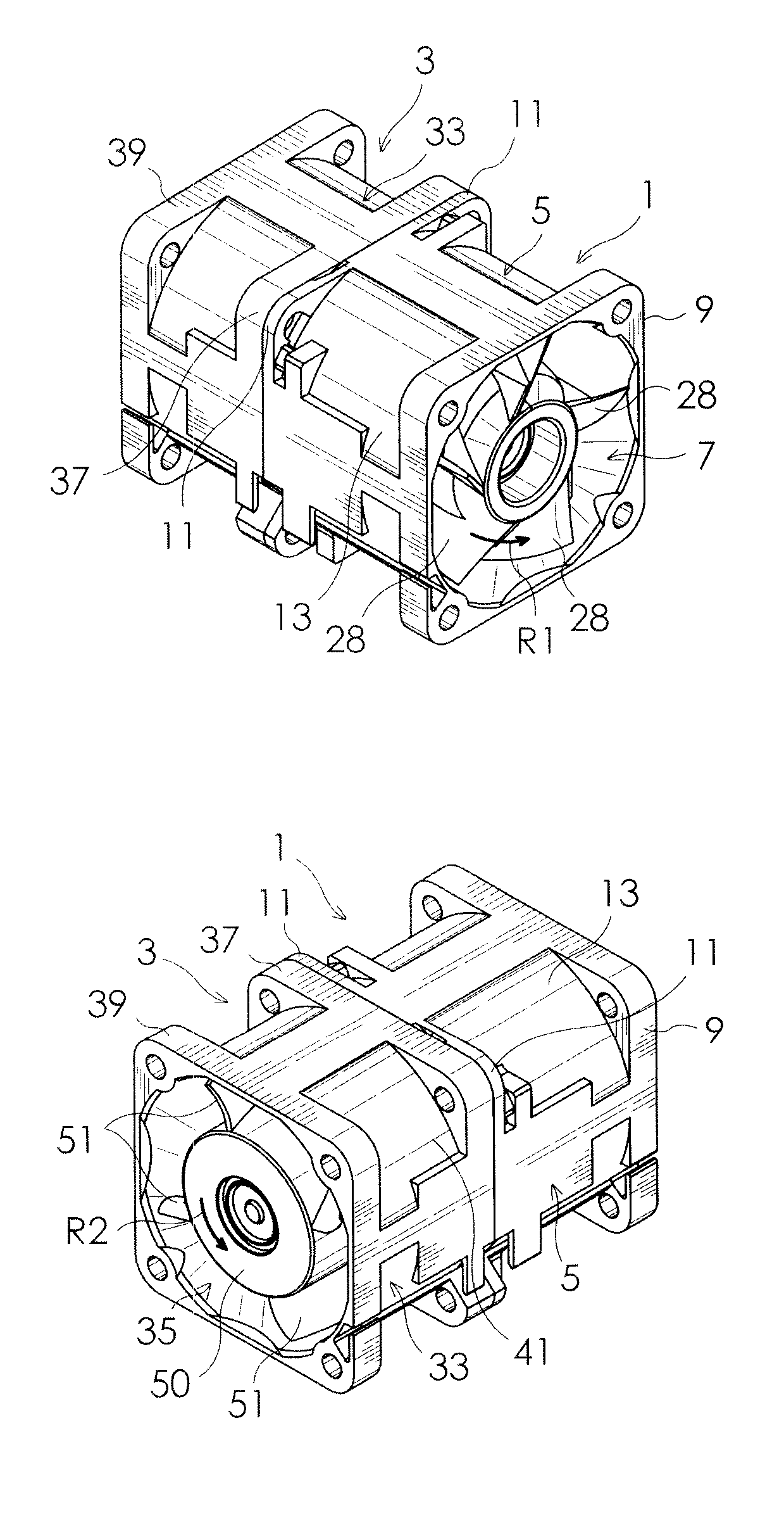
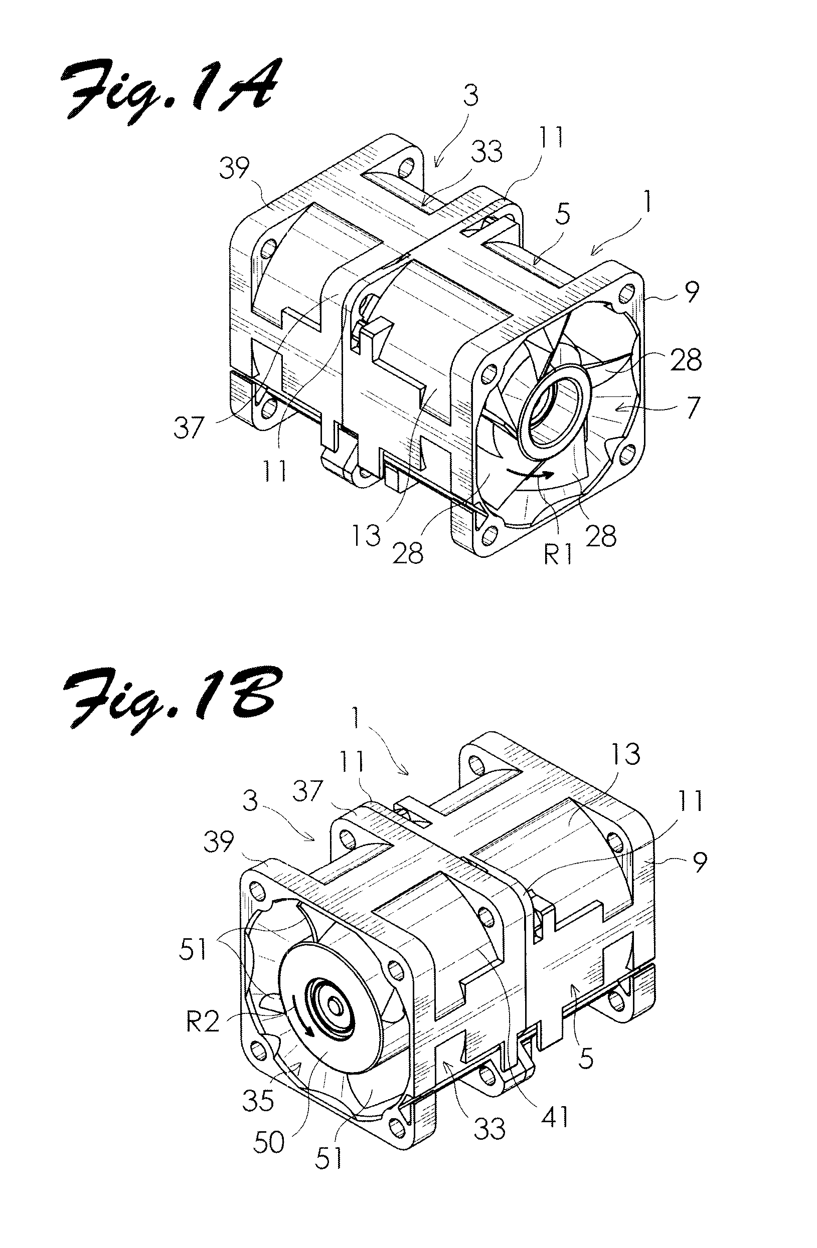
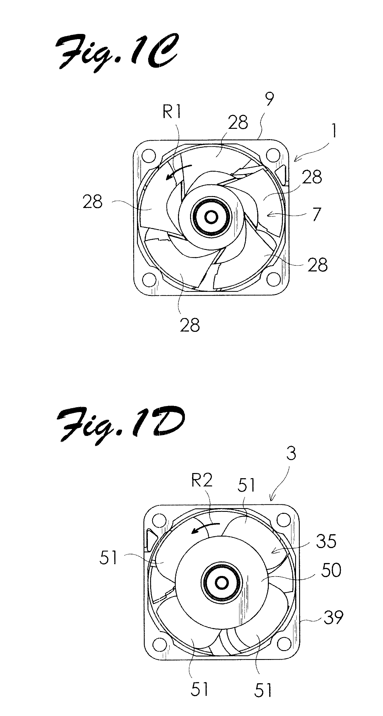
[0025]A counter-rotating axial flow fan according to an embodiment of the present invention will be described below with reference to the drawings. FIG. 3 illustrates the schematic configuration of a counter-rotating axial flow fan according to the embodiment of the present invention. The configuration of the counter-rotating axial flow fan according to the embodiment is basically the same as that of the conventional counter-rotating axial flow fan shown in FIGS. 1 and 2 except for the shape of a front impeller 7′, the shape of a rear impeller 35′, and the shape of stationary blades 61′. Thus, in the embodiment, components in FIG. 3 that are the same as those forming the counter-rotating axial flow fan shown in FIGS. 1 and 2 are denoted by the same reference numerals as those given in FIGS. 1 and 2, and different components in FIG. 3 are denoted by reference numerals obtained by suffixing an apostrophe (') to the reference numerals given in FIGS. 1 and 2, and detailed descriptions a...
PUM
 Abstract
Description
Claims
Application Information