Attractant system for mounting to an insect trapping apparatus

Active Publication Date: 2005-12-08
WOODSTREAM CORP +1
View PDF14 Cites 10 Cited by
  • Summary
  • Abstract
  • Description
  • Claims
  • Application Information

AI Technical Summary

Benefits of technology

[0006] The attractant system comprises a housing defining at least a first chamber and a second chamber. The chambers may have any configuration and additional chambers may be provided. The housing is constructed to be mounted to the apparatus in any suitable manner. For example, in the MOSQUITO MAGNET apparatuses, the housing could be mounted in the outflow tube so as to allow the attrac

Problems solved by technology

If the attractants were communicated with each other during this time period, they may diffuse, intermingle, and react with eac

Method used


Image

  • Attractant system for mounting to an insect trapping apparatus
  • Attractant system for mounting to an insect trapping apparatus
  • Attractant system for mounting to an insect trapping apparatus

Examples


Example

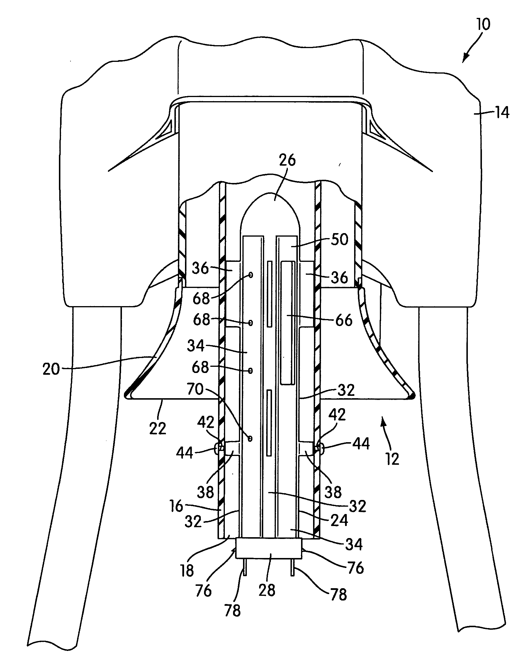
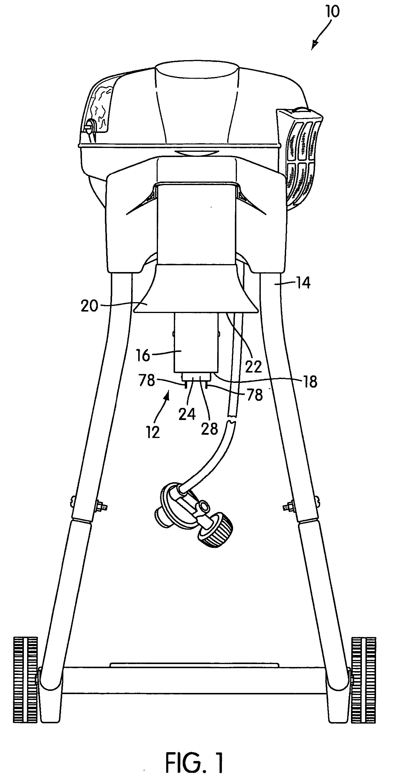
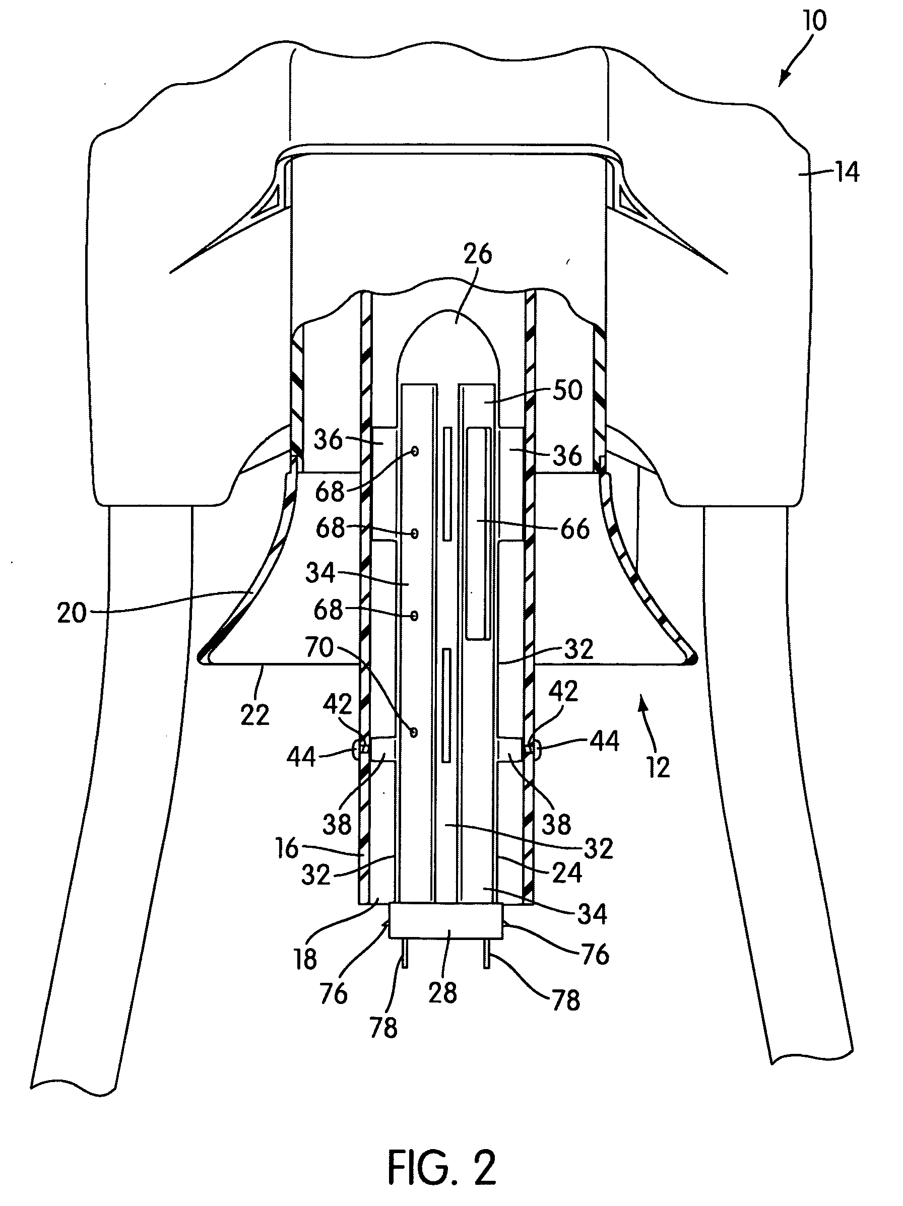
[0022]FIG. 1 shows an example of an insect trapping apparatus, generally indicated at 10, with which the attractant system, generally indicated at 12, may be used. The apparatus 10 shown in FIG. 1 is the MOSQUITO MAGNET LIBERTY, which is described in U.S. patent application No. 2003 / 0084604 A1 filed Oct. 4, 2002. The attractant system 12 may also be used with any other type of insect trapping apparatus, such as other combustion based types, and non-combustion based types, such as the CDC light trap. For other patents / applications illustrating examples of such apparatuses, reference may be made to U.S. Pat. Nos. 6,286,249, 6,145,243, and U.S. patent application. No. 10 / 445,245, filed May 27, 2003; Ser. No. 10 / 445,199, filed May 27, 2003; and Ser. No. 10 / 686,815, filed Oct. 17, 2003. Each of the patent applications mentioned above, or otherwise mentioned anywhere else in the present application, are hereby incorporated by reference into the present application in their entirety.

[0023...


PUM


Abstract

The present invention relates to an attractant system for mounting to an insect trapping apparatus.

Description

FIELD OF THE INVENTION [0001] The present invention relates to an attractant system for mounting to an insect trapping apparatus. BACKGROUND OF THE INVENTION [0002] Insect trapping apparatuses are well known in the art. For example, American Biophysics Corporation sells insect trapping apparatuses under the trademark MOSQUITO MAGNET that use combustion to generate a CO2 laden outflow for attracting insects. Reference may be made to U.S. Pat. No. 6,145,243 and U.S. patent application No. 2003 / 0084604 A1 for details of the operation of such traps, the entirety of each of which is hereby incorporated into the present application by reference. [0003] It is also known to supplement these traps with chemical attractants to better attract flying insects, such as mosquitoes, no-see-ums, etc. The MOSQUITO MAGNET apparatuses attract insects not only by emitting an outflow with a high CO2 content from the combustion, it also uses octenol to enhance the attractiveness of the outflow. [0004] Som...

Claims


Application Information

Patent Timeline
IPC IPC(8): A01M1/02A01M1/06
CPCA01M1/02A01M2200/012A01M1/06A01M1/023
Inventor DURAND, EMMA A.DUNNE, RICHARD B.CAO, MIAOYONGLIU, CUIXIA
Owner WOODSTREAM CORP
Why Eureka
Try Eureka