Anemometer calibration method and wind turbine

a technology of anemometer and calibration method, which is applied in the direction of instruments, electric generator control, machines/engines, etc., can solve the problems of inaccurate reading of such a nacelle anemometer and inability to individually calibrate conventional anemometers

Inactive Publication Date: 2008-12-18
GENERAL ELECTRIC CO
View PDF4 Cites 66 Cited by
  • Summary
  • Abstract
  • Description
  • Claims
  • Application Information

AI Technical Summary

Problems solved by technology

However, the readings of such a nacelle anemometer are often inaccurate.
One reason

Method used


Image

  • Anemometer calibration method and wind turbine
  • Anemometer calibration method and wind turbine
  • Anemometer calibration method and wind turbine

Examples


Embodiment Construction

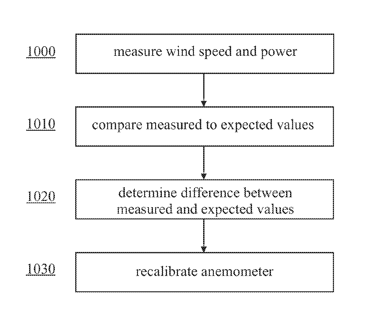
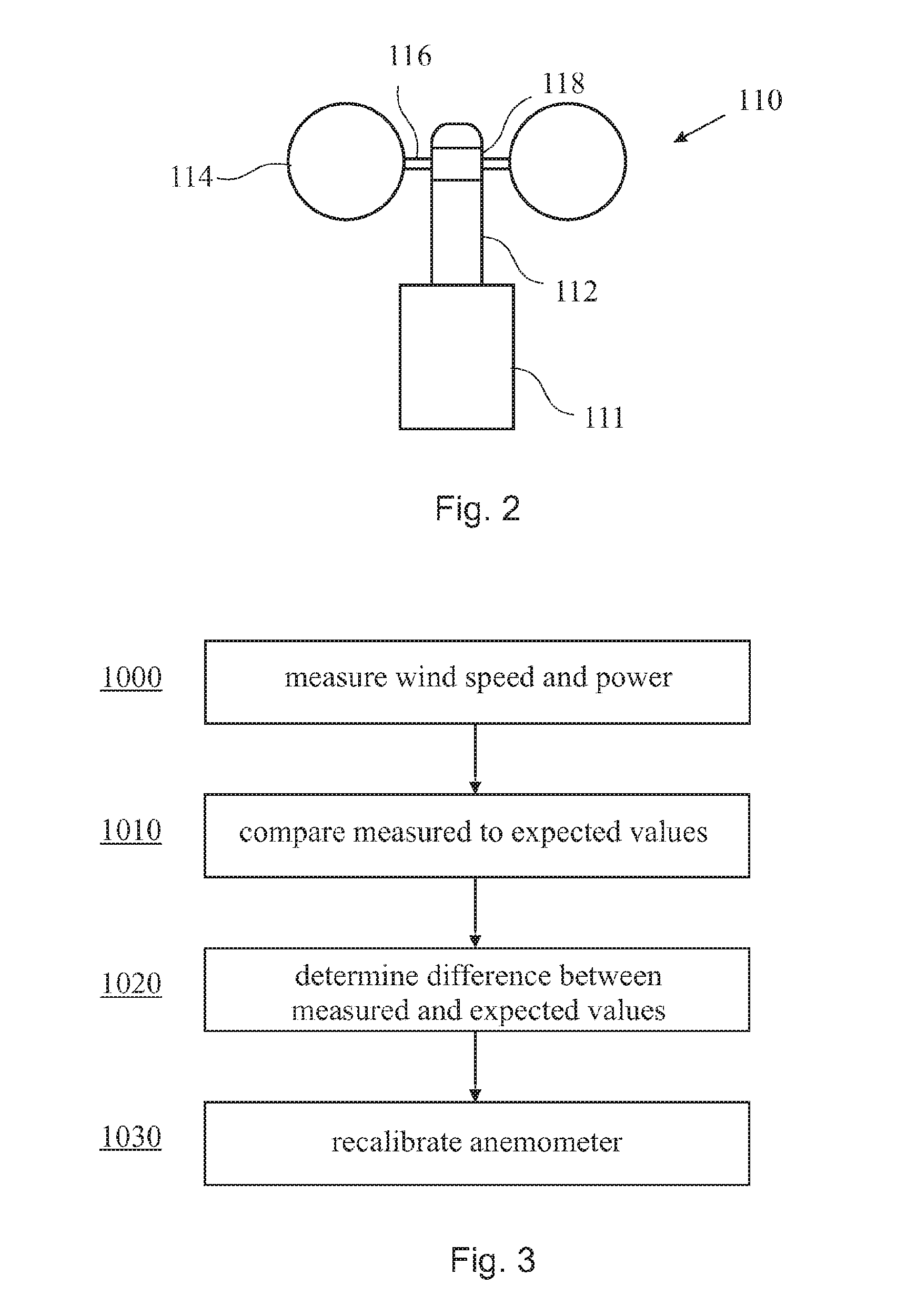
[0019]Reference will now be made in detail to the various embodiments of the invention, one or more examples of which are illustrated in the figures. Each example is provided by way of explanation of the invention, and is not meant as a limitation of the invention. For example, features illustrated or described as part of one embodiment can be used on or in conjunction with other embodiments to yield yet a further embodiment. It is intended that the present invention includes such modifications and variations.

[0020]In the following, embodiments of the present invention will be described in which generated output power is used as a wind speed-dependent turbine variable. However, it will be understood by those skilled in the art that the inventive method described below can similarly be applied to any other turbine variable that depends on the wind speed. In this context, it should be understood that the term “wind speed-dependent” should include that the variable is influenced by the...


PUM


Abstract

A method for re-calibrating an anemometer of a wind turbine is provided, the method comprising the steps of obtaining pairs of measured values of wind speed and a wind-speed dependent turbine variable; comparing said measured value pairs to pairs of wind speed and the turbine variable obtained from an expected turbine variable curve of the wind turbine to determine a difference between a measured wind speed value and an expected wind speed value for a given turbine variable value; and adjusting a calibration function of said anemometer on the basis of said determined difference.

Description

BACKGROUND OF THE INVENTION[0001]The present invention relates to a method for calibrating an anemometer, in particular for in situ calibration of an anemometer[0002]In the field of wind energy, anemometers are typically used to measure the wind speed at a specific wind turbine site since wind speed is an important control parameter for the operation of wind turbines. Typically, a wind turbine is equipped with at least one anemometer mounted on the nacelle. However, the readings of such a nacelle anemometer are often inaccurate. One reason for the inaccuracy is that conventional anemometers are not individually calibrated. Instead, the same linear average calibration function is typically used for all sensors and turbines of the same type, which does not account for variation in ambient conditions, site conditions, or site specific turbine parameter settings.BRIEF DESCRIPTION OF THE INVENTION[0003]In view of the above, the present invention provides a method for re-calibrating an an...

Claims


Application Information

Patent Timeline
IPC IPC(8): G01P21/00F03D9/00F03D7/00
CPCF05B2260/80F05B2270/32F05B2270/802G01P5/07G01P21/025F03D17/00F05B2260/821
Inventor SIEBERS, THOMASKOOIJMAN, HENK-JANROGERS, DONALD
Owner GENERAL ELECTRIC CO
Why Eureka
Try Eureka