Printhead integrated circuit with actuators close to exterior surface

a technology of actuators and integrated circuits, applied in printing and other directions, can solve the problems of fluid drag and pulse energy dissipation, and achieve the effects of reducing the volume of ink, limiting the print speed, and fast refilling tim

Inactive Publication Date: 2008-12-18
SILVERBROOK RES PTY LTD
View PDF34 Cites 4 Cited by
  • Summary
  • Abstract
  • Description
  • Claims
  • Application Information

AI Technical Summary

Benefits of technology

[0041]Preferably, each of the droplet ejectors has a chamber in which the actuator is positioned, the chamber having a volume less than 30,000 microns cubed. In a further preferred form, the volume is less than 25,000 microns cubed. Low energy ejection of ink droplets generates little, if any, excess heat in the printhead. A build up of excess heat in the printhead imposes a limit on the nozzle firing frequency and thereby limits the print speed. The IJ30 printhead is self cooling (the heat generated by the thermal actuator is removed from the printhead with the ejected drop). In this case, the print speed is only limited by the rate at which the ink can be supplied to the printhead or the speed that the media substrate can be fed past the printhead. Reducing the volume of the ink chambers reduces the volume of ink in which the heat can dissipate. However, a reduced volume ink chamber has a fast refill time and relies solely on capillary action. As the actuator is configured for low energy input, the reduced volume of ink does not cause problems for heat dissipation.
[0042]Preferably, the printhead IC has a back face that is opposite said one face on which the printhead surface layer is formed, and at least one supply conduit extending from the back face to the array of droplet ejectors such that the at least one supply conduit is in fluid communication with a plurality of the droplet ejectors in the array. In a further preferred form, the printhead IC has a plurality of the supply conduits and drive circuitry for providing the actuators with power, the drive circuitry having patterned layers of metal separated by interleaved layers of dielectric material, the layers of metal being interconnected by conductive vias, wherein the drive circuitry extends between the plurality of supply conduits. Supplying the array of droplet ejectors with ink from the back face of the printhead IC instead of along the front face provides more room to the electrical contacts and drive circuitry. This in turn, provides the scope to increase the density of droplet ejectors per unit area on the printhead IC.

Problems solved by technology

Any redirection of the pressure pulse through the ink as the drop is ejected from the nozzle aperture induces fluidic drag and some of the pulse energy dissipates.

Method used


Image

  • Printhead integrated circuit with actuators close to exterior surface
  • Printhead integrated circuit with actuators close to exterior surface
  • Printhead integrated circuit with actuators close to exterior surface

Examples


Embodiment Construction

IJ26

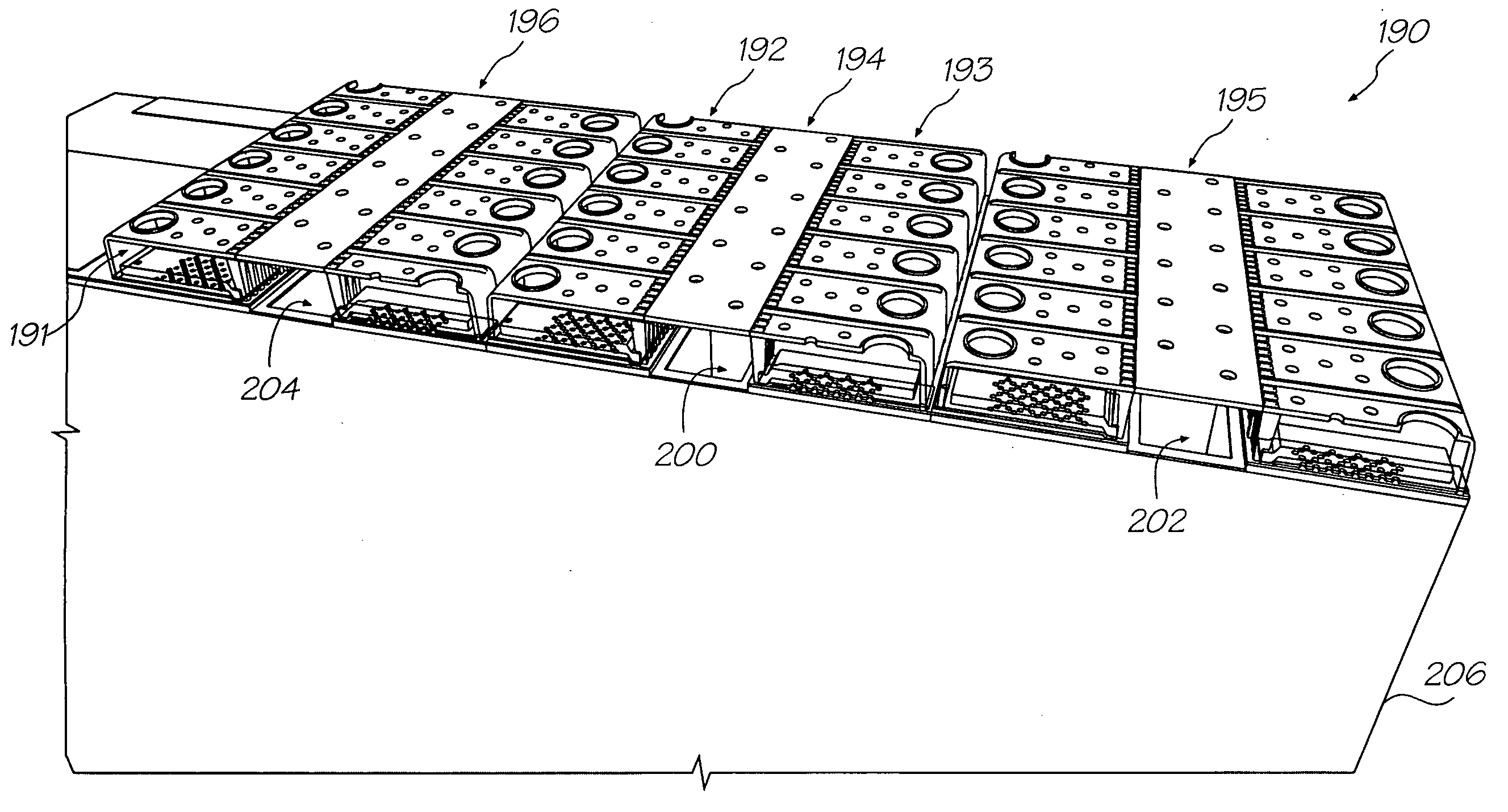
[0078]The embodiment shown in FIGS. 1 to 15 is referred to by the Applicant and within the Assignee company, as the IJ26 printhead. In this printhead, shape memory materials are utilized to construct an actuator suitable for injecting ink from the nozzle of an ink chamber.

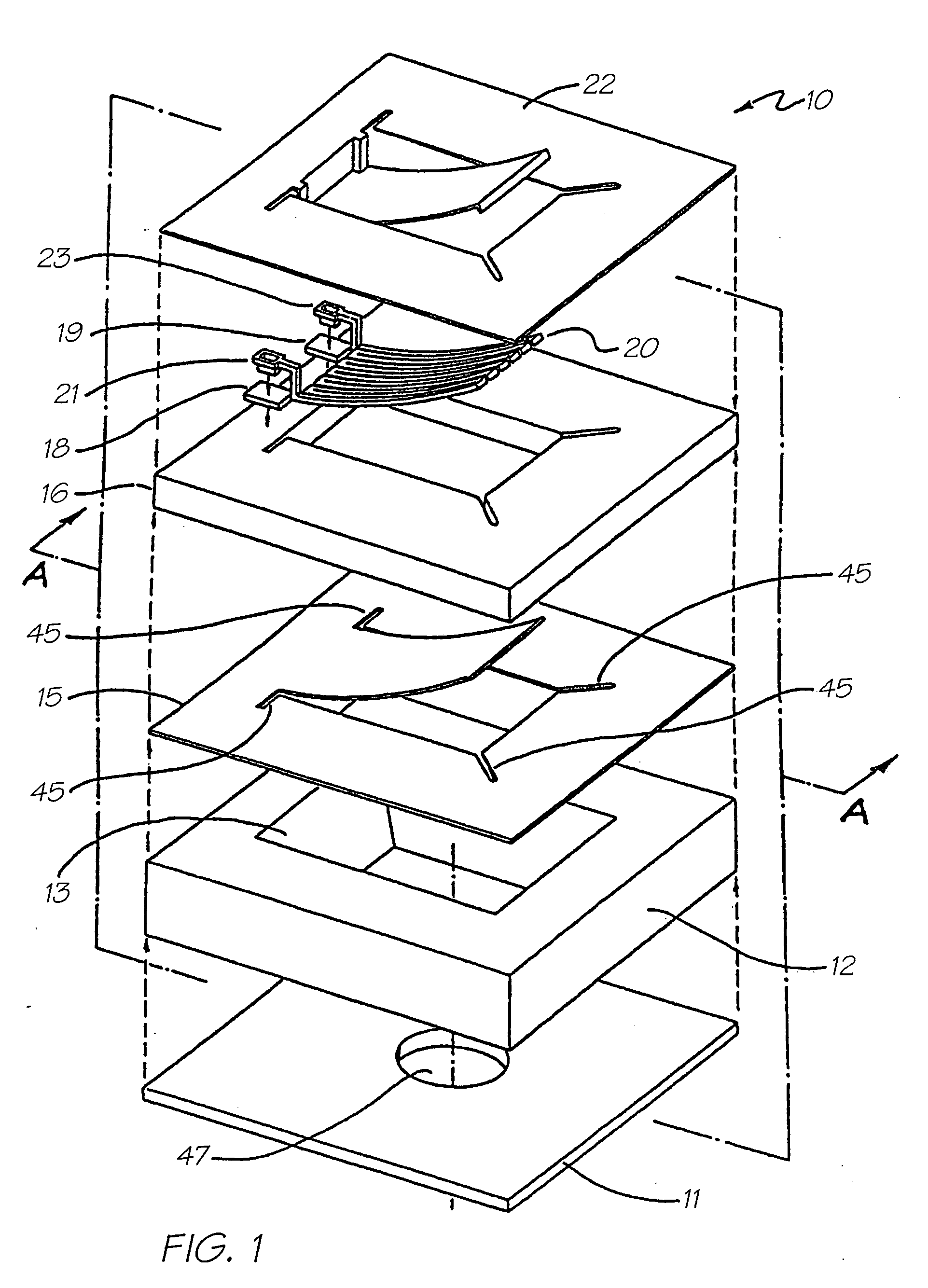
[0079]FIG. 1 illustrates an exploded perspective view 10 of a single ink jet nozzle as constructed in accordance with the preferred embodiment. The ink jet nozzle 10 is constructed from a silicon wafer base utilizing back etching of the wafer to a boron doped epitaxial layer. Hence, the ink jet nozzle 10 comprises a lower layer 11 which is constructed from boron doped silicon. The boron doped silicon layer is also utilized a crystallographic etch stop layer. The next layer comprises the silicon layer 12 that includes a crystallographic pit 13 having side walls etched at the usual angle of 54.74 degrees. The layer 12 also includes the various required circuitry and transistors for example, CMOS layer (not shown)...


PUM


Abstract

An inkjet printhead that has an array of droplet ejectors supported on a printhead integrated circuit (IC). Each of the droplet ejectors has a nozzle aperture and an actuator for ejecting a droplet of ink through the nozzle aperture. The actuator in each of the droplet ejectors is configured to generate a pressure pulse in a quantity of ink adjacent the nozzle aperture, the pressure pulse being directed towards the nozzles aperture such that the droplet of ink is ejected through the nozzle aperture. The actuator is positioned in the droplet ejector such that it is less than 30 microns from an exterior surface of the printhead surface layer.

Description

CROSS REFERENCES TO RELATED APPLICATIONS[0001]The present application is a continuation in part of U.S. application Ser. No. 11 / 525,857 filed 25 Sep. 2006, which is in turn a continuation of U.S. application Ser. No. 11 / 064,011 filed on Feb. 24, 2005, now issued as U.S. Pat. No. 7,178,903 which is a continuation of U.S. application Ser. No. 10 / 893,380 filed on Jul. 19, 2004, now issued U.S. Pat. No. 6,938,992, which is a continuation of U.S. application Ser. No. 10 / 307,348 filed on Dec. 2, 2002, now issued as U.S. Pat. No. 6,764,166, which is a continuation of U.S. application Ser. No. 09 / 113,122 filed on Jul. 10, 1998, now issued as U.S. Pat. No. 6,557,977, the entire contents of which are herein incorporated by reference.[0002]The following Australian provisional patent applications are hereby incorporated by reference. For the purposes of location and identification, US patents / patent applications identified by their US patent / patent application serial numbers (USSN) are listed a...

Claims


Application Information

Patent Timeline
Patent Type & Authority Applications(United States)
IPC IPC(8): B41J2/155
CPCB41J2/14427B41J2/1628B41J2/1629B41J2/1631B41J2/1632B41J2/1635B41J2/1639B41J2/1642B41J2/1643B41J2/1645B41J2/1648
Inventor SILVERBROOK, KIA
Owner SILVERBROOK RES PTY LTD
Why Eureka
Try Eureka