Printhead With Low Power Actuators

Inactive Publication Date: 2009-11-05
ZAMTEC +1
View PDF49 Cites 0 Cited by
  • Summary
  • Abstract
  • Description
  • Claims
  • Application Information

AI Technical Summary

Benefits of technology

[0021]Incorporating the drive circuitry and the droplet ejectors onto the same supporting substrate reduces the number of electrical connections needed on the printhead IC and the resistive losses when transmitting power to the actuators. The circuitry on the printhead IC needs to have more than just power and ground metal layers in order to provide the necessary drive FETs, shift registers and so on. However, each metal layer can be thinner and fabricated using well known and efficient techniques employed in standard semiconductor fabrication. Overall, this yields production efficiencies in time and cost.
[0054]Increasing the speed of the media substrate relative to the printhead, whether the printhead is a scanning or pagewidth type, reduces the time needed to complete printjobs.

Problems solved by technology

Accurate registration between the thermal actuators and the nozzles can be problematic.
These problems effectively restrict the size of the nozzle array in any one monolithic plate and corresponding actuator substrate.
Furthermore, differential thermal expansion between the nozzle plate and the actuator substrate create greater misalignments as the array sizes increase.
Given these limits on nozzle array size, pagewidth printheads using this two-part design are impractical.
The complexity of this arrangement make such printers commercially unrealistic.
Each technology may have its own advantages and disadvantages in the areas of cost, speed, quality, reliability, power usage, simplicity of construction operation, durability and consumables.

Method used


Image

  • Printhead With Low Power Actuators
  • Printhead With Low Power Actuators
  • Printhead With Low Power Actuators

Examples


Embodiment Construction

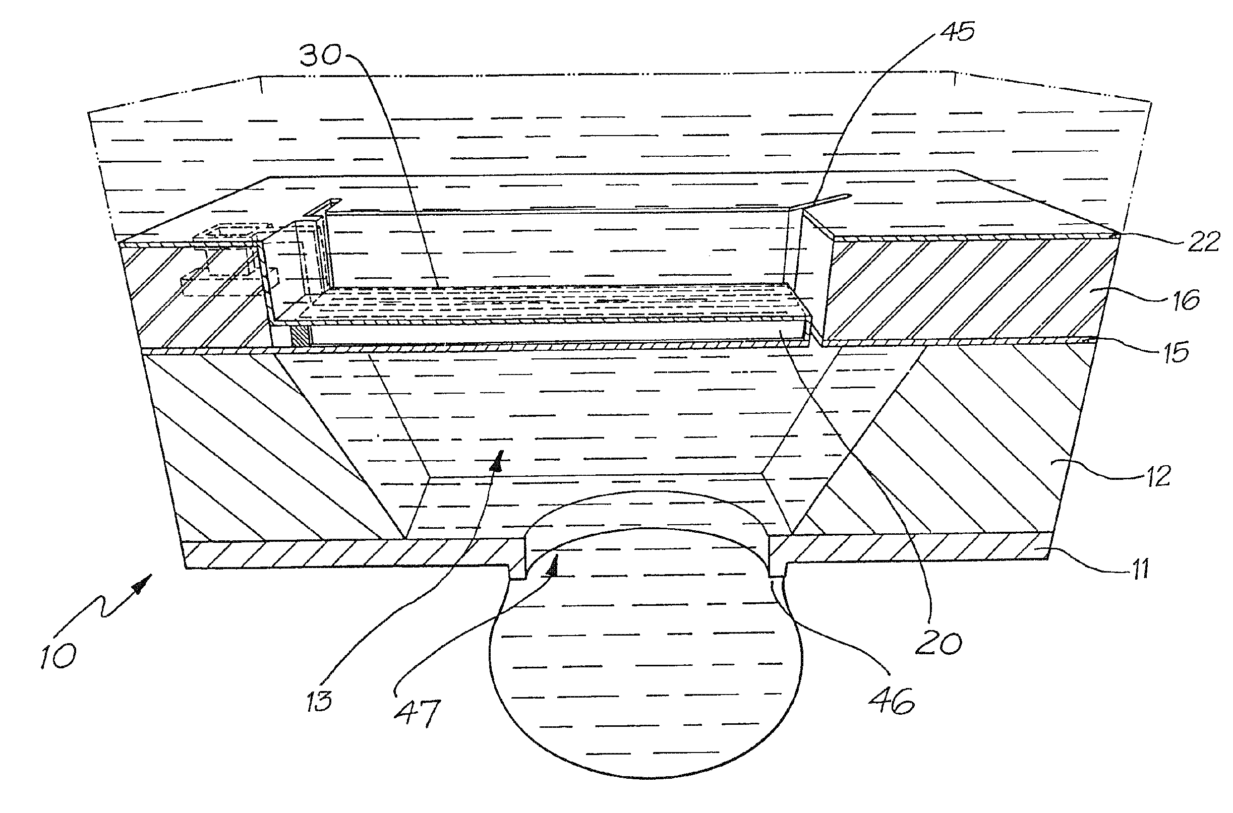
[0076]In the preferred embodiment, shape memory materials are utilised to construct an actuator suitable for injecting ink from the nozzle of an ink chamber.

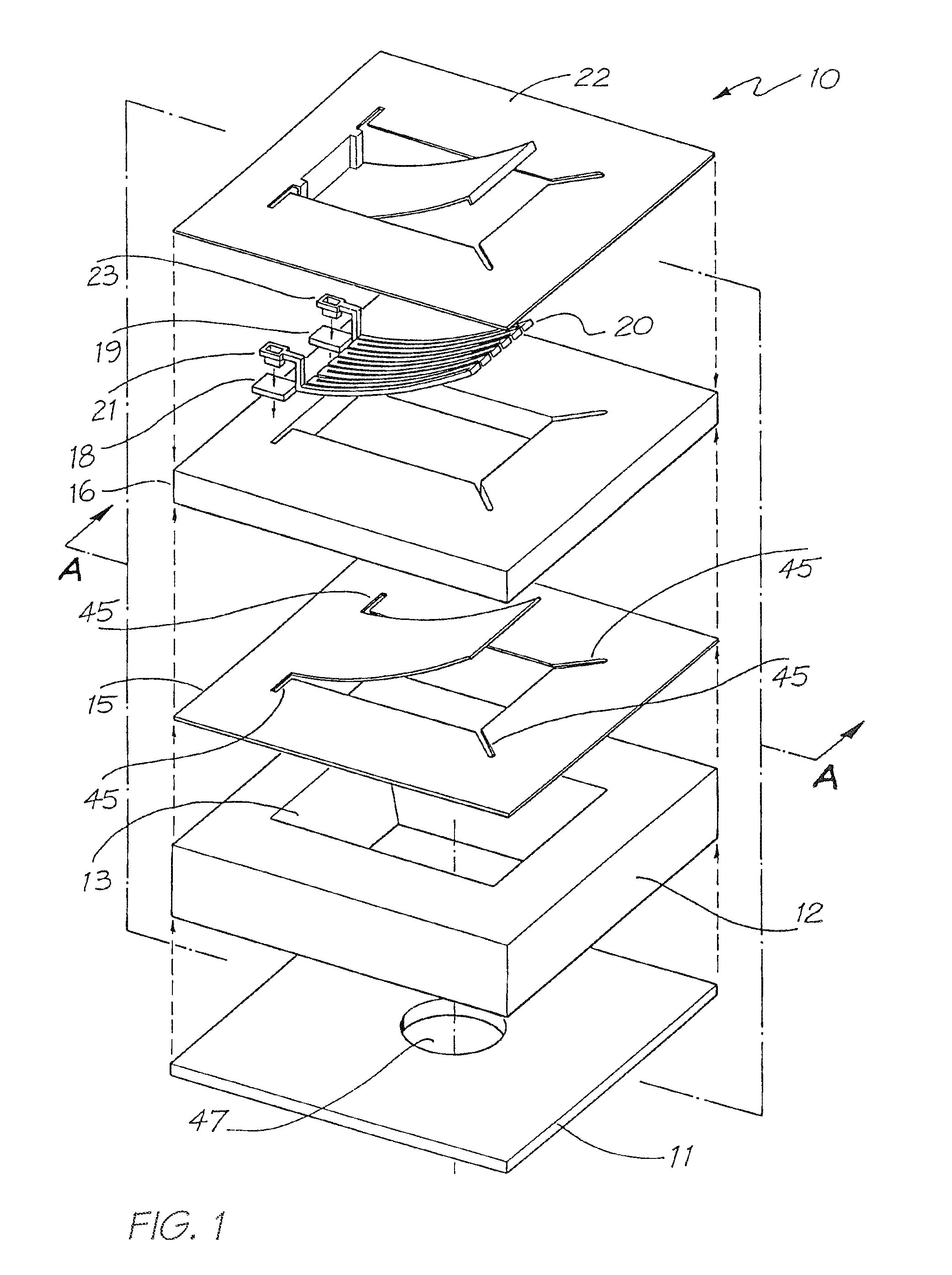
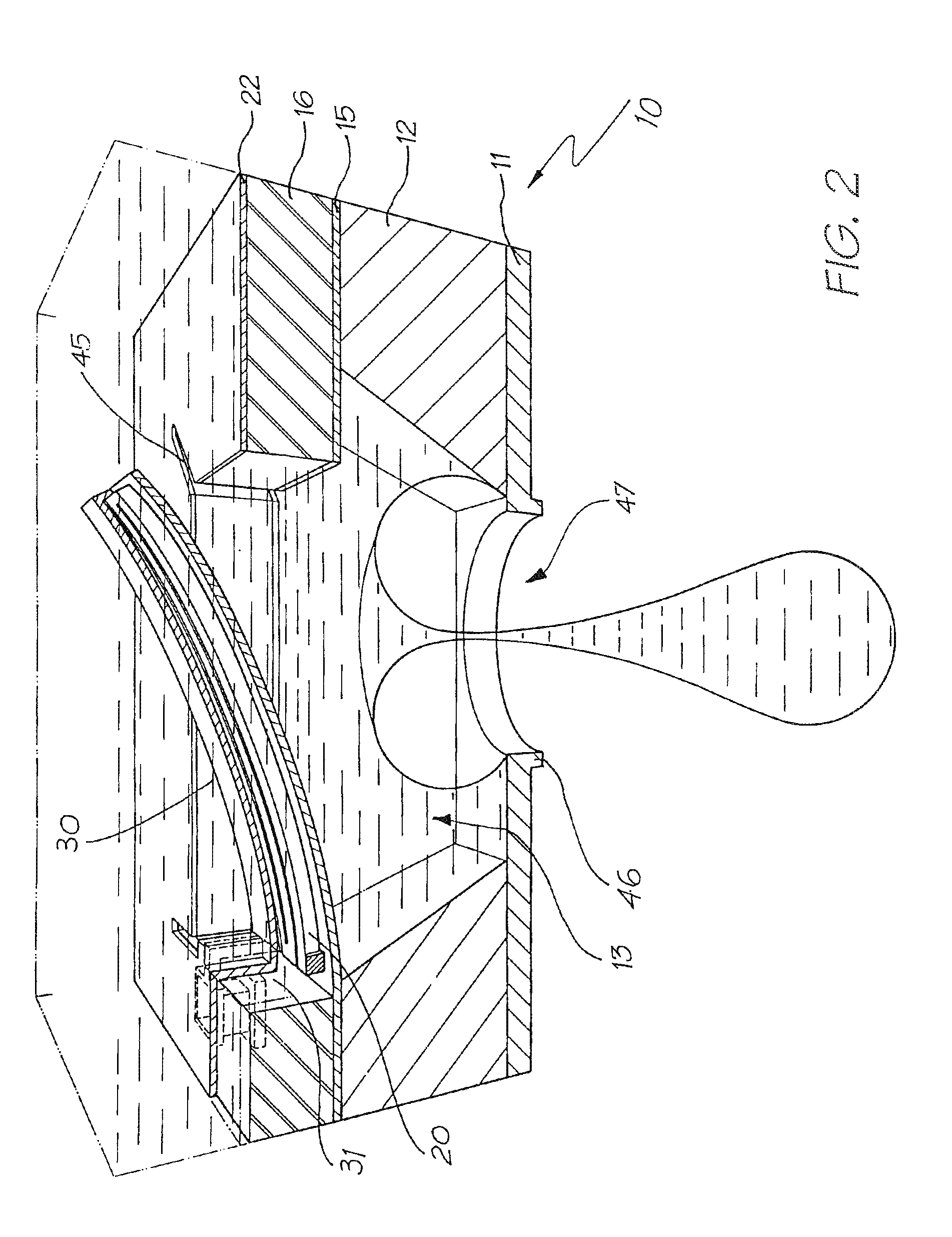
[0077]Turning to FIG. 1, there is illustrated an exploded perspective view 10 of a single ink jet nozzle as constructed in accordance with the preferred embodiment. The ink jet nozzle 10 is constructed from a silicon wafer base utilizing back etching of the wafer to a boron doped epitaxial layer. Hence, the ink jet nozzle 10 comprises a lower layer 11 which is constructed from boron-doped silicon. The boron doped silicon layer is also utilized as a crystallographic etch stop layer. The next layer comprises the silicon layer 12 that includes a crystallographic pit that defines a nozzle chamber 13 having side walls etched at the conventional angle of 54.74 degrees. The layer 12 also includes the various required circuitry and transistors for example, a CMOS layer (not shown). After this, a 0.5-micron thick thermal silicon oxide la...


PUM


Abstract

An inkjet printhead that has an array of droplet ejectors supported on a printhead integrated circuit (IC). Each of the droplet ejectors has a nozzle aperture and an actuator for ejecting a droplet of ink through the nozzle aperture. When printing, each of the actuators has an average power consumption less than 150 mW during activation.

Description

CROSS REFERENCE TO RELATED APPLICATIONS[0001]The present application is a continuation-in-part of U.S. application Ser. No. 11 / 926,109 filed on Oct. 28, 2007, which is a continuation of U.S. application Ser. No. 11 / 778,572 filed on Jul. 16, 2007, which is a continuation of U.S. application Ser. No. 11 / 349,074 filed on Feb. 8, 2006, now issued U.S. Pat. No. 7,255,424, which is a continuation of U.S. application Ser. No. 10 / 982,789 filed on Nov. 8, 2004, now issued U.S. Pat. No. 7,086,720, which is a continuation of U.S. application Ser. No. 10 / 421,823 filed on Apr. 24, 2003, now issued U.S. Pat. No. 6,830,316, which is a continuation of U.S. application Ser. No. 09 / 113,122 filed on Jul. 10, 1998, now issued U.S. Pat. No. 6,557,977, all of which are herein incorporated by reference.CROSS REFERENCES TO RELATED APPLICATIONS[0002]The following US Patents and US Patent Applications are hereby incorporated by cross-reference.US Patent / Patent ApplicationIncorporated by Reference:Docket No.6...

Claims


Application Information

Patent Timeline
IPC IPC(8): B41J29/38
CPCB41J2/14427B41J2/1626B41J2/1648B41J2/1642B41J2/1631
Inventor SILVERBROOK, KIA
Owner ZAMTEC
Why Eureka
Try Eureka