Electric Anti-Impact Lock with Spring Accumulator

a technology of spring accumulator and electric lock, which is applied in the direction of building locks, constructions, and lock casings, can solve the problems of weak lock pin structure, difficult to enforce the lock pin structure, and other problems of common electromagnetic locks, so as to reduce the cost of products, facilitate manufacture, and simplify the lock structure

Inactive Publication Date: 2008-12-25
MIN HAO
View PDF11 Cites 23 Cited by
  • Summary
  • Abstract
  • Description
  • Claims
  • Application Information

AI Technical Summary

Benefits of technology

[0016]1. This invention solves the problem of weakness existing in the current electromagnetic locks in current market, the new electric anti-impact lock with spring accumulator can guarantee no any break or distortion under 1000 kg impact. The safety grade is increased greatly.
[0018]3. This invention simplifies the lock structure, makes easy for the manufacture, and reduces the costs for products.

Problems solved by technology

For example, when electromagnet is on power or off power, a lock pin is plugged into or pulled out from a slipping block, which controls a keeper to open or lock a door, but the lock pin is weak in structure.
It is difficult to enforce the structure of the lock pin as the electromagnet force is relatively weak and the keeper is relatively heavy.
This is a main hidden trouble of the safety box locked by common electromagnetic lock.
Also, the common electromagnetic locks have other problems.
It means that although tests of password, fingerprint and key are passed, the lock still cannot be opened.
This is caused by shortages of the structure of the common electromagnet lock.
As a result, the keeper cannot be withdrawn.
However, the electromagnet becomes power off at the time of releasing the door, the keeper still cannot be withdrawn.

Method used


Image

  • Electric Anti-Impact Lock with Spring Accumulator
  • Electric Anti-Impact Lock with Spring Accumulator
  • Electric Anti-Impact Lock with Spring Accumulator

Examples


Embodiment Construction

[0026]The accompanying drawings facilitate understanding of the preferred embodiments of this invention.

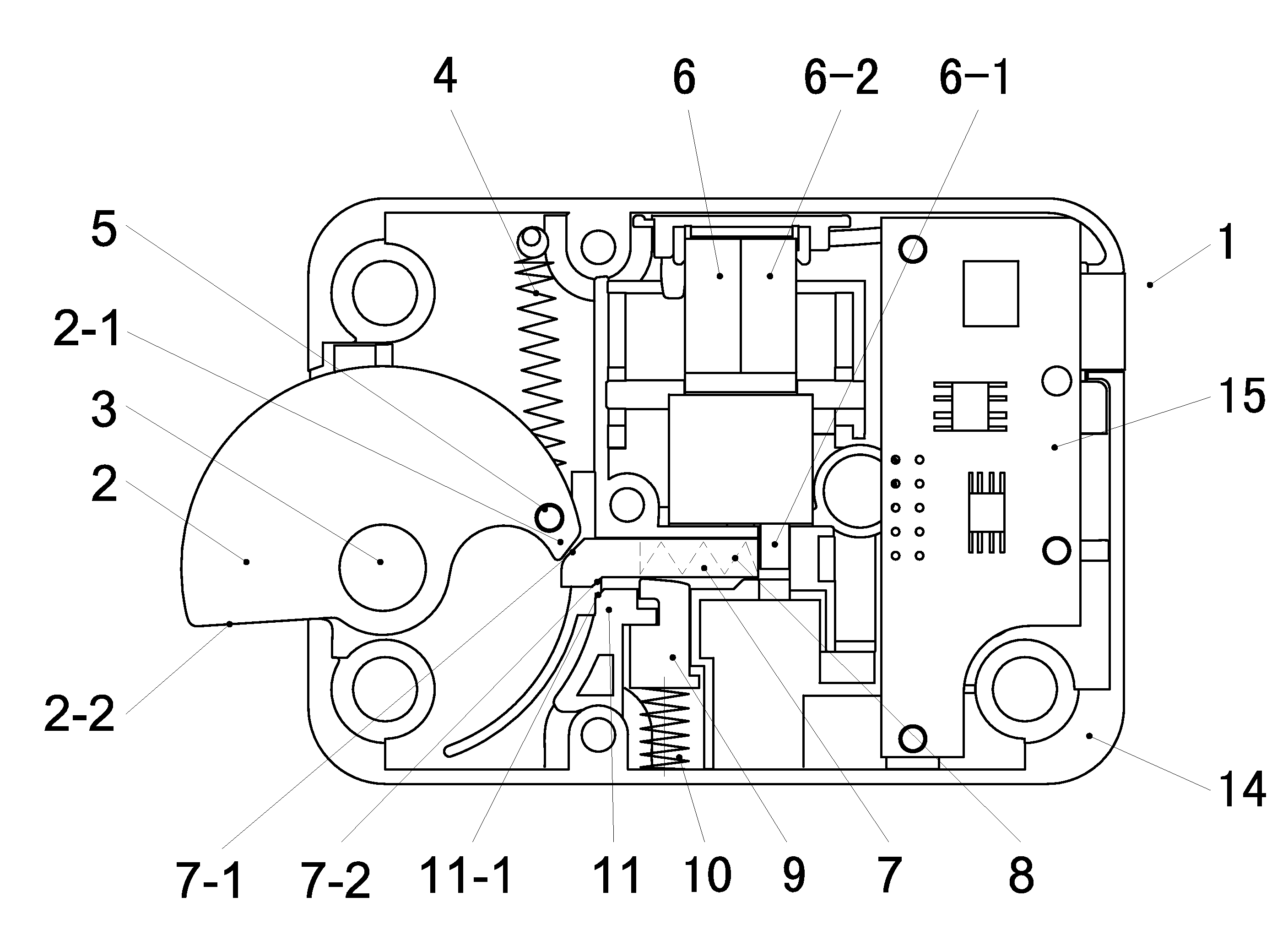
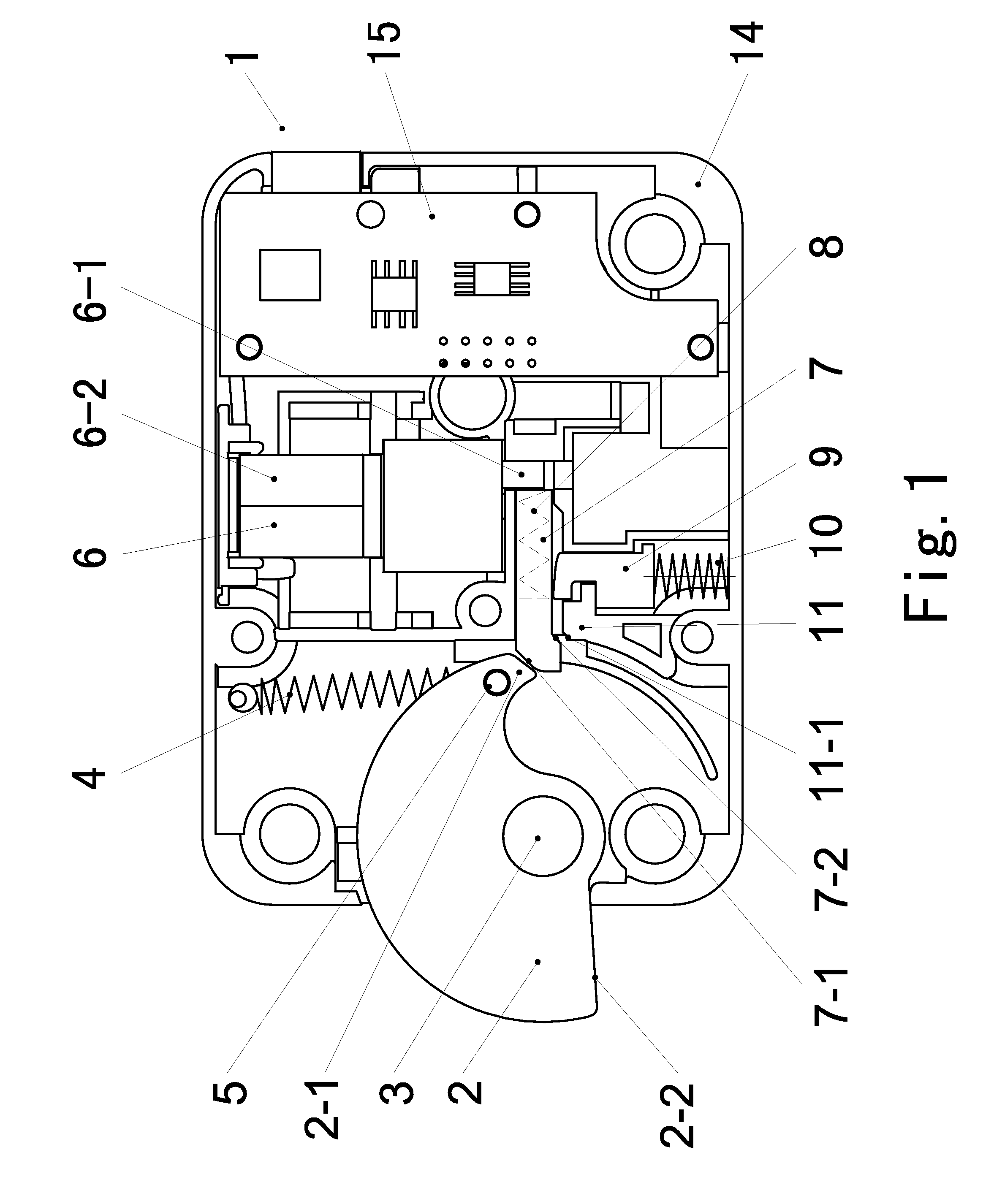
[0027]Refer to FIG. 1; it shows an electric anti-impact lock 1 with spring accumulator, which includes a lock shell 14, a keeper 2 for locking door, a device for locking keeper 2, an anti-impact device and a device for locking block bar.

[0028]The keeper 2 is pivoted on a keeper pivot 3 in the shell 14, has a cam shape with a latch portion 2-2 at one end and a tail portion 2-1 at other end. The latch portion 2-2 has a beeline outline and the tail portion 2-1 has a bevel face. One end of a first spring 4 is connected with the tail portion 2-1 and other end is connected with the shell 14. The first spring 4 is an extension spring, whose force pulls the keeper 2 to turn out of the shell 14.

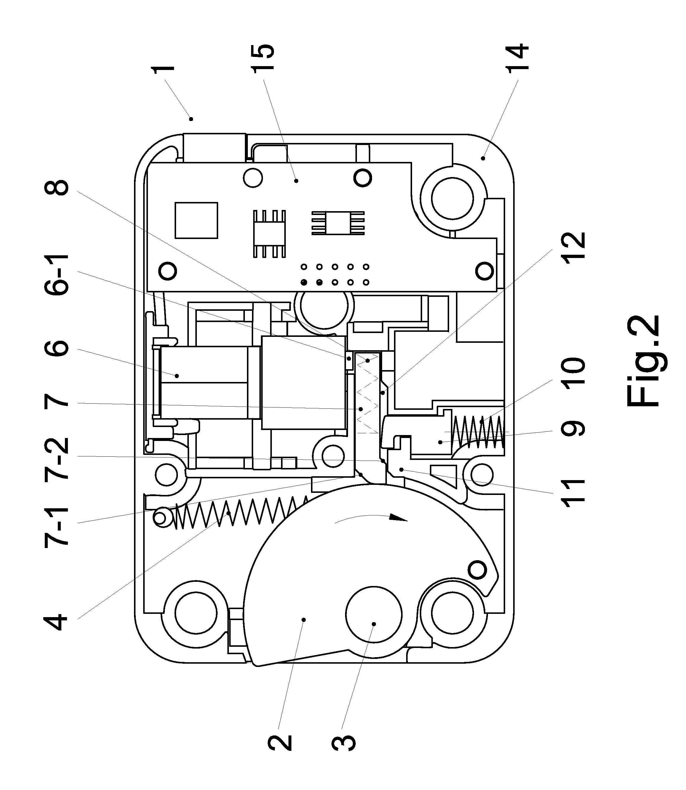
[0029]The device for locking keeper includes a groove 12, a block bar 7 is slideable in the groove 12, a second spring 8 is a compress spring, one end of the second spring 8 is against the block bar...


PUM


Abstract

An electric anti-impact lock with spring accumulator comprises a lock shell; a pivot keeper for locking door with a latch portion and a tail portion, the door can be opened when the latch portion pivoting into the shell, the door being locked when the latch portion pivoting outside the shell; a device for locking keeper comprising a slideable block bar, the keeper is locked when the slideable block bar being against the tail portion, the keeper is turnable when the slideable block being moved away; a anti-impact device having a reinforce structure, which bears a impact from the door through the keeper and the block bar; and a device for locking block bar is a block pin device with spring accumulator, the block pin shoots out to stop moving of the block bar when power on, thereby, the door being locked, the block pin withdrawing to free the stop when power on in reverse pole, the door can be opened. The new lock solves the problems of weakness and lock death for current electromagnetic locks in market. The cost of the new lock is lower and the manufacture is easy.

Description

CROSS REFERENCE TO THE RELATED PATENT APPLICATION[0001]This patent application is a continuation in part application of the pending U.S. application Ser. No. 11 / 624,192 with a filing date Jan. 17, 2007, which claims the priority of the Chinese patent application No. 200620077575.4 with a filing date of Sep. 25, 2006.FIELD OF THE INVENTION[0002]This invention relates to a new style of an electrical lock, especially relates a new style of the electrical lock having strong anti-impact ability.BACKGROUND OF THE INVENTION[0003]Currently, most of the safety boxes, which use electromagnetic locks with fingerprint identification for safety purpose are used by banks, jewelry business, or firearms business etc. Unauthorized users cannot open the safety boxes, which are locked by the electromagnetic locks with fingerprint identification. However, the ability for anti-impact is a main concern in selecting electromagnetic locks. Sometimes, locks are required to suffer a strong impact over one to...

Claims


Application Information

Patent Timeline
Patent Type & Authority Applications(United States)
IPC IPC(8): E05B49/00
CPCE05B9/00E05B17/2084E05B47/0012E05B47/0603E05B63/0013E05B65/0075E05B2047/0093Y10T70/7068Y10T70/7102
Inventor MIN, HAO
Owner MIN HAO
Why Eureka
Try Eureka