Hole puncher
- Summary
- Abstract
- Description
- Claims
- Application Information
AI Technical Summary
Benefits of technology
Problems solved by technology
Method used
Image


Examples
Embodiment Construction
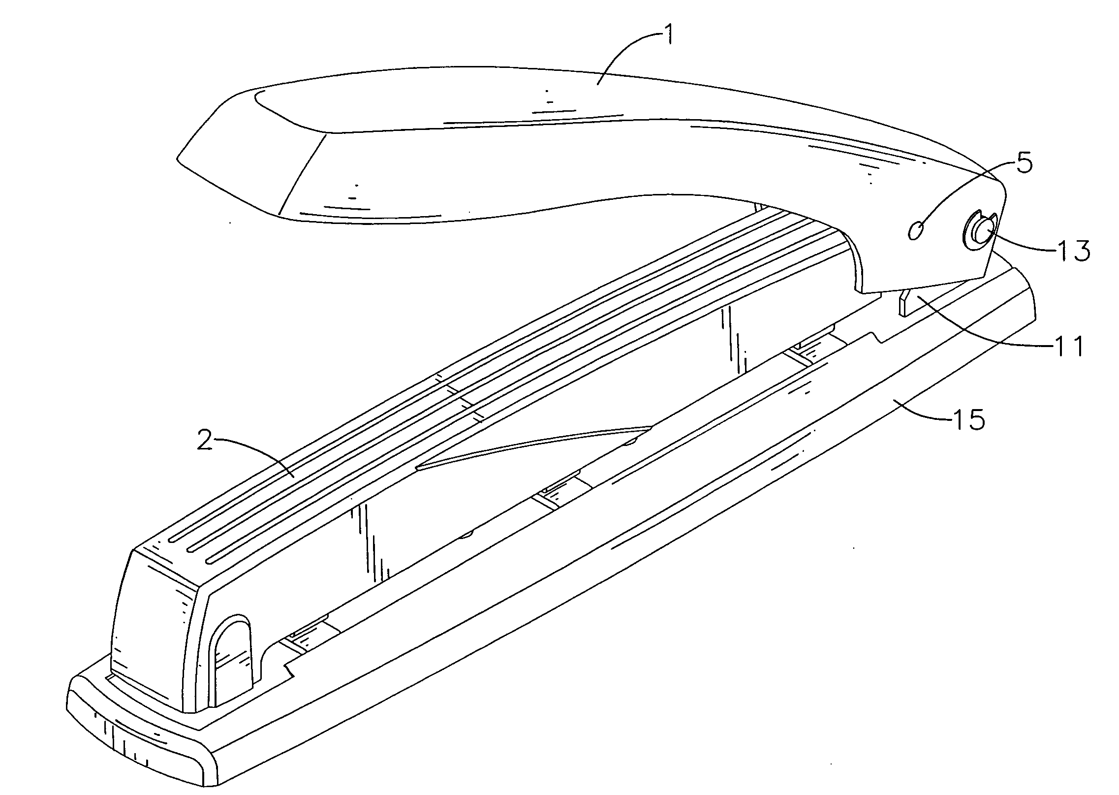
[0018]With reference to FIGS. 1, 5, 6 and 7, a hole puncher in accordance with the present invention comprises a base (10, 10B), multiple cutter brackets (9), multiple cutters (7), multiple springs (8), a linkage, an activating member (3) and a handle (1, 1C). The hole puncher may further comprise a lock device.
[0019]With further reference to FIGS. 2 and 3, the base (10, 10B) has a front end, a rear end, a bottom surface, a top surface, multiple through holes (14), a linkage bracket (12, 12B) and a handle bracket (11, 11B) and may further have a bottom cover (15).
[0020]The through holes (14) are defined through the base (10, 10B) in a row.
[0021]The linkage bracket (12, 12B) is attached to the front end of the base (10, 10B) and may have two wings. Each wing has a pivot hole (120). In a first embodiment of the hole puncher, the linkage bracket (12) is U-shaped, is mounted on the bottom surface of the base (10) with the wings extending up through the base (10) out of the top surface. ...
PUM
 Abstract
Description
Claims
Application Information