Fastening structure and seal box with the fastening structure

Inactive Publication Date: 2008-05-15
CHEN YU HSIN
View PDF2 Cites 58 Cited by
  • Summary
  • Abstract
  • Description
  • Claims
  • Application Information

AI Technical Summary

Benefits of technology

[0010]The fastening structure of the invention is a fastening structure disposed at the periphery of a cover, comprising: at least one fastening flange extended outward from the periphery of the cover, a latch portion disposed under the fastening flange for latching and fixing the cover; and a hinge portion for connecting the fastening flange at the periphery of the cover, wherein the hinge portion has a plurality of sections of crevices for reducing a hinge area where the fastening flange is connected to the cover.
[0011]The thickness of the hinge portion is smaller than that of the fastening flange, so that the fastening flange can be folded and stacked onto the cover by the hinge portion.
[0012]A sealed box of a preferred embodiment of the invention comprises: a cover, a plurality of fastening flanges disposed at the periphery of the cover, and each fastening flange having at least one latch portion disposed under the fastening flange; and a hinge portion for connecting the fastening flange to the periphery of the cover. The thickness of the hinge portion is smaller than that of the fastening flange, such that the fastening flange can be folded and stacked onto the cover by the hinge portion. The hinge portion has a plurality of sections of crevices for reducing a hinge area that connects the fastening flange with the cover and a container having a latch structure disposed proximate to the top edge, and the latch structure works together with the latch portions for latching and fixing the cover.
[0013]The latch structure includes a sunken latch portion for pressing and hooking the latch portion

Problems solved by technology

Further, the design of the fixing protrusion 111 no longer can ke

Method used


Image

  • Fastening structure and seal box with the fastening structure
  • Fastening structure and seal box with the fastening structure
  • Fastening structure and seal box with the fastening structure

Examples


Embodiment Construction

[0025]The present invention will now be described in more detail hereinafter with reference to the accompanying drawings as follows:

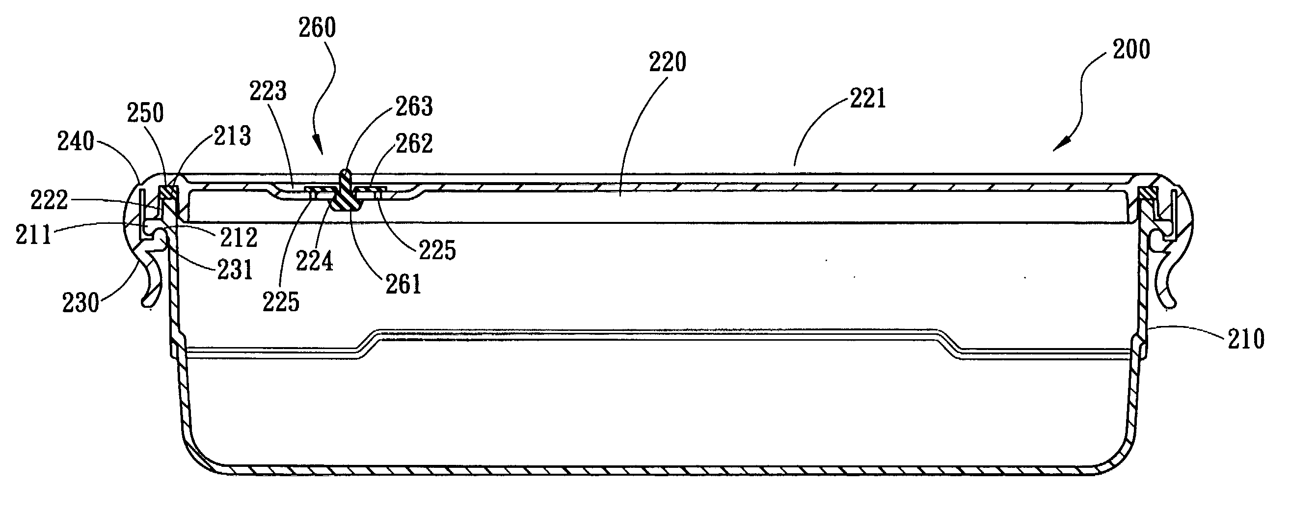
[0026]Referring to FIG. 4A to 6, a plastic sealed box 200 in accordance with a preferred embodiment of the present invention. The sealed box 200 is made of a plastic material and comprises a container 210 and a cover 220. The container 210 has a latch structure 211 protruded from a position proximate to the periphery of the top edge 213 of the container 210 and a latch portion 212 under the latch structure 211. The periphery of the cover 220 has a plurality of fastening flanges 230 (each is a rectangular sealed box 200 with four sides), and each fastening flange 230 is connected to the periphery of the cover 220 through a hinge portion 240 for bending and turning the fastening flange 230 with respect to the periphery of the cover 220 through the hinge portion 240. The hinge portion 240 forms a plurality of sections of crevices 242, such as 0.2 mm crevic...


PUM

PropertyMeasurementUnit
Thicknessaaaaaaaaaa
Widthaaaaaaaaaa
Stress optical coefficientaaaaaaaaaa

Abstract

The present invention discloses a fastening structure having a fastening flange extended outward from the periphery of a cover, and the fastening flange has a latch portion under the fastening flange for latching and fixing the cover; and a hinge portion for connecting the fastening flange at the periphery of the cover, and the hinge portion has a plurality of sections of crevices for reducing a hinge area that connects the fastening flange to the cover. The invention also discloses a sealed box that includes the fastening structure, and a container having a latch structure disposed at a top edge of the container and used together with the latch portion for latching and fixing the cover. Without changing the thickness of the hinge portion, the invention can save efforts for the operation of the sealed box while maintaining the stress of the hinge portion.

Description

FIELD OF THE INVENTION[0001]The present invention relates to a plastic box, and more particularly to a fastening device of a box body and a plastic container with the fastening device.BACKGROUND OF THE INVENTION[0002]Referring to FIGS. 1 to 3 for a traditional structure of a sealed box having a container for containing objects or storing food, the plastic sealed box 100 includes a sealed box 100 having a container 110 and a cover 120. The container 110 includes a plurality of fixing protrusions 111 disposed at the top of the container 110 and a plurality of fastening flanges 130 disposed at the periphery of the cover 120, and the fastening flanges 130 are connected to the periphery of the cover 120 by a hinge portion 140 and turned through the hinge portion 140. The fastening flange 130 includes a locking slot 131 corresponding to the fixing protrusion 111 for latching and fixing the protrusion 111, such that the fastening flange 130 can latch the cover 120 to the container 110.[000...

Claims


Application Information

Patent Timeline
IPC IPC(8): B65D41/16B65D45/16B65D41/18B65D51/16
CPCB65D81/2038B65D45/32
Inventor CHEN, HSIN-YU
Owner CHEN YU HSIN
Why Eureka
Try Eureka