Electric actuator

a technology of electric actuators and actuators, which is applied in the direction of mechanical equipment, manufacturing tools, and manufacturing, etc., can solve the problems of increasing the axial length of the electric actuator, the inability to efficiently air-cool the wave generator, etc., and achieves the effect of efficient air-cooling, improving the cooling performance of the electric motor, and restraining the elliptical cam

Inactive Publication Date: 2008-12-25
HONDA MOTOR CO LTD
View PDF11 Cites 5 Cited by
  • Summary
  • Abstract
  • Description
  • Claims
  • Application Information

AI Technical Summary

Benefits of technology

[0007]The present invention has been made with a view of the background described above, and it is an object of the present invention to provide a compact electric actuator capable of efficiently air-cooling not only an electric motor but also a wave generator of a wave gear speed reducer connected to the electric motor, while obviating an increase of an axial length.
[0009]According to the present invention, the air blown in by the vane portion air-cools the electric motor and the air blown in by the vane portion also flows through the holes formed in the wave generator. Thus, the wave generator is also efficiently air-cooled. Further, the partitioning portion between the holes formed in the wave generator constitutes the vane portion, which is different from the one in which the vane portions are protrusively installed on the side surface of the wave generator, which side surface is adjacent to the motor, so that the vane portions do not lead to an increased axial interval between the electric motor and the wave generator. This arrangement makes it possible to obviate an increase of the axial length of the electric actuator.
[0010]The wave generator is generally comprised of an elliptical cam and a flexible ball bearing which is externally fitted to the cam. In the wave generator, the elliptical cam is provided with the aforesaid holes and the aforesaid vane portions. Meanwhile, when the external gear is elliptically flexed so as to be partially meshed with the internal gear, the elliptical cam is subjected to a large reaction force in the direction of the elliptical long axis thereof. For this reason, desirably, at least one of the width in the circumferential direction of the vane portion formed on a portion which matches the elliptical long axis of the elliptical cam and the width in the radial direction of an outer circumferential portion which matches the elliptical long axis of the elliptical cam is set to be larger than the width in the circumferential direction of the vane portion formed on a portion which matches the elliptical short axis of the elliptical cam or the width in the radial direction of an outer circumferential portion which matches the elliptical short axis of the elliptical cam, thereby increasing the rigidity of the elliptical cam in the direction of the elliptical long axis. With this arrangement, it is possible to restrain the elliptical cam from developing compressive deformation in the direction of the elliptical long axis due to a reaction force acting on the elliptical cam. This makes it possible to restrain the external gear from failing to successfully mesh with the internal gear.
[0011]Further, in the present invention, preferably, an internal space of the electric motor wherein a coil is disposed is in communication with an internal space of the speed reducer and air flows into the internal space of the electric motor by an air blow supplied by the vane portion of the wave generator. This arrangement directly air-cools the coil disposed in the internal space of the electric motor, leading to further improved cooling performance of the electric motor. Further preferably, an air cooling passage is formed in the stator of the electric motor, and air flows through the air cooling passage by the air blow supplied by the vane portion of the wave generator. This allows the stator to be efficiently air-cooled.
[0012]Meanwhile, the direction of the air blown in by the vane portion of the wave generator switches between the direction toward the electric motor from the speed reducer and the direction toward the speed reducer from the electric motor, depending on whether the wave generator or the electric motor rotates in the forward direction or the reverse direction. If the rotational direction of the electric motor repeatedly switches between the forward direction and the reverse direction at short intervals, hot air moves back and forth between the electric motor and the speed reducer. This resultantly restrains the inflow of outside air into the electric motor, preventing the electric motor from being successfully air-cooled.
[0013]Therefore, in the present invention, an air passage in communication with a portion wherein the wave generator is disposed is preferably provided with a one-way valve. Thus, only when the electric motor rotates in either the forward direction or the reverse direction, air flows in one direction which corresponds to the particular rotational direction. Therefore, even if the rotational direction of the electric motor repeatedly switches between the forward direction and the reverse direction at short intervals, hot air will not move back and forth between the electric motor and the speed reducer. Thus, outside air is securely introduced into the electric motor to air-cool the electric motor.

Problems solved by technology

This arrangement makes it impossible to efficiently air-cool the wave generator.
In addition, providing the vane portions protrusively on the side surface of the wave generator that is adjacent to the motor requires that the axial interval between the electric motor and the wave generator be increased to accommodate the protruding vane portions, inevitably resulting in an increased axial length of the electric actuator.

Method used


Image

  • Electric actuator
  • Electric actuator
  • Electric actuator

Examples


second embodiment

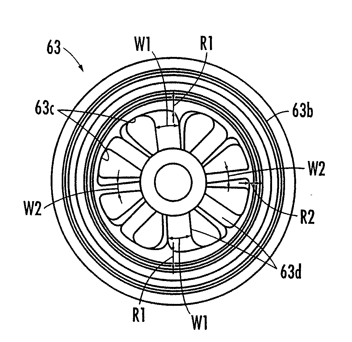
[0053]FIG. 11 and FIG. 12 illustrate a wave generator 63 of a second embodiment taking the aforesaid need into account. In the present embodiment, a circumferential width W1 of a vane portion 63d formed in the portion that matches the elliptical long axis of an elliptical cam 63a of the wave generator 63 is set to be larger than a circumferential width W2 of the vane portion 63d formed in the portion that matches the elliptical short axis of the vane portion 63d formed in the portion that matches the elliptical short axis thereof. In addition, a radial width R1 of the outer circumferential portion that matches the elliptical long axis of the elliptical cam 63a is set to be larger than a radial width R2 of the outer circumferential portion that matches the elliptical short axis thereof. This enhances the rigidity of the elliptical cam 63a in the direction of the elliptical long axis. It is therefore possible to restrain the elliptical cam 63a from developing compressive deformation i...

third embodiment

[0057] therefore, the internal space 6b of the drive pulley 6a, which provides an air passage in communication with the portion where the wave generator 63 is disposed, is provided with a one-way valve 16, which permits only an air flow moving from the opening 421e toward the portion where the wave generator 63 is disposed. The one-way valve 16 is composed of a cylindrical valve seat 16a vertically provided around the opening 421e and a rubber valve element 16c installed on a supporting rod 16b vertically provided in the valve seat 16a such that the valve element 16c is seated on the valve seat 16a. Further, a filter 16d serving also as a supporter for the valve element 16c is installed in the valve seat 16a.

[0058]With this arrangement, when the electric motor 5 runs in the forward direction, a negative pressure generated in the internal space 6b of the drive pulley 6a due to the air blown from the speed reducer toward the electric motor 5 by the vane portions 63d of the wave gener...


PUM


Abstract

An electric actuator comprised of an electric motor and a wave gear speed reducer connected to the electric motor efficiently air-cools the electric motor and a wave generator of the speed reducer and obviates the need for increasing the axial length of the actuator. The wave generator has a plurality of holes penetrating in the axial direction, the holes being arranged with intervals provided in the circumferential direction. A partitioning portion between the holes constitutes a vane portion which blows air in the axial direction. An internal space wherein a coil of the electric motor is disposed is in communication with an internal space of the speed reducer, and the vane portion blows air into the internal space of the electric motor. An air cooling passage is formed in a stator of the electric motor such that air flows into the air cooling passage when the vane portion blows air.

Description

BACKGROUND OF THE INVENTION[0001]1. Field of the Invention[0002]The present invention relates to an electric actuator composed of an electric motor and a wave gear speed reducer connected to the electric motor.[0003]2. Description of the Related Art[0004]Hitherto, as a speed reducer, a wave gear type speed reducer has been known. This type of speed reducer includes an internal gear, a flexible annular external gear, and a wave generator which elliptically flexes the external gear to partially mesh the external gear with the internal gear. When an electric actuator is constructed by connecting a wave gear speed reducer to an electric motor, the wave generator is connected to a rotor of the electric motor, and either the internal gear or the external gear is secured to the case of the speed reducer. Thus, the other gear is rotatively slowed down as the wave generator rotates.[0005]Conventionally, there has been known such an electric actuator with vane portions protrusively provided o...

Claims


Application Information

Patent Timeline
Patent Type & Authority Applications(United States)
IPC IPC(8): H02K9/06
CPCA61H3/008B25J9/0006Y10T74/19H02K9/06H02K7/116
Inventor NODA, TATSUYA
Owner HONDA MOTOR CO LTD
Why Eureka
Try Eureka