Moveable platform for a laptop computer

a laptop computer and mobile technology, applied in the field of laptop computers, can solve the problems of poor ergonomics, difficult typing or other keyboard activities for users with flat keyboards, and often require the user to assume uncomfortable and unhealthy positions on the laptop computer, so as to reduce eye strain and reduce wrist sprain.

Inactive Publication Date: 2008-12-25
JACOBS CARL V +1
View PDF9 Cites 39 Cited by
  • Summary
  • Abstract
  • Description
  • Claims
  • Application Information

AI Technical Summary

Benefits of technology

[0026]According to the present invention, a moveable platform for a laptop computer supports the laptop computer on an angled support base of the moveable platform. The angled support base will tilt the keyboard of the base structure of the laptop computer relative to the computer user to reduce wrist sprain and elevate the display monitor of the laptop computer relative to the computer user to reduce eyestrain.
[0033]These non-metallic materials for the ball, ball bearings and cavity of the spherical roller assemblies provide smooth quiet operation with minimal frictional resistance and are non-abrasive to the desktop surface.
[0037]Alternately, the spherical roller assemblies can be mounted on the lower surface of the laptop computer to platform move the laptop computer around the desktop without the use of a separate platform. A braking mechanism at the front of the laptop computer can lock the laptop computer in position on the desktop.

Problems solved by technology

Due to that design, laptop computers often require the user to assume uncomfortable and unhealthy positions for extended periods of time during use of the laptop computer.
Laptop computers have relatively small and ergonomically incorrect keyboards.
Typing or other keyboard activities are difficult for the user with a flat keyboard over extended periods of time.
The display monitor for a laptop computer on a desktop or tabletop surface is also ergonomically incorrect.
The monitor will be below the eye level of the user causing eyestrain, and neck and back strain during the longer periods of operation that have become common.
The processing unit, hard drive, optical drives and battery power sources of the laptop computer generate substantial heat during operation of the laptop.
However, in a laptop computer there is very little room for large fans or open airspace, so heat is dissipated through the bottom surface of the base structure of the laptop computer.
The thin airgap may not be able to dissipate the heat over prolonged use of the computer causing the laptop to overheat or at least impair the operation of the computer.
The ‘feet’ may scratch, dull, or otherwise mar the surface when being moved across the desktop.
The ‘feet’ are also noisy when being moved along the surface of the desktop.
However, the conventional revolving members of these prior art patents are noisy when being used to move the laptop computer.
The conventional revolving members can also mar the surface by scratching or dulling the shine of the desktop or tabletop when the laptop computer is being moved.
The flat mobility assembly also has the same heat dissipation problems as the flat bottom surface of the base structure of the laptop computer.
The thin airgap between the flat mobility assembly and the desktop does not effectively dissipate the heat from the laptop computer.
Similarly, the flat mobility assembly also has the same keyboard and display monitor ergonomical problems as the laptop computer.
The flat keyboard will cause hand problems for a prolonged user of the laptop computer and the low display monitor will cause eyestrain for the user.

Method used


Image

  • Moveable platform for a laptop computer
  • Moveable platform for a laptop computer
  • Moveable platform for a laptop computer

Examples


Embodiment Construction

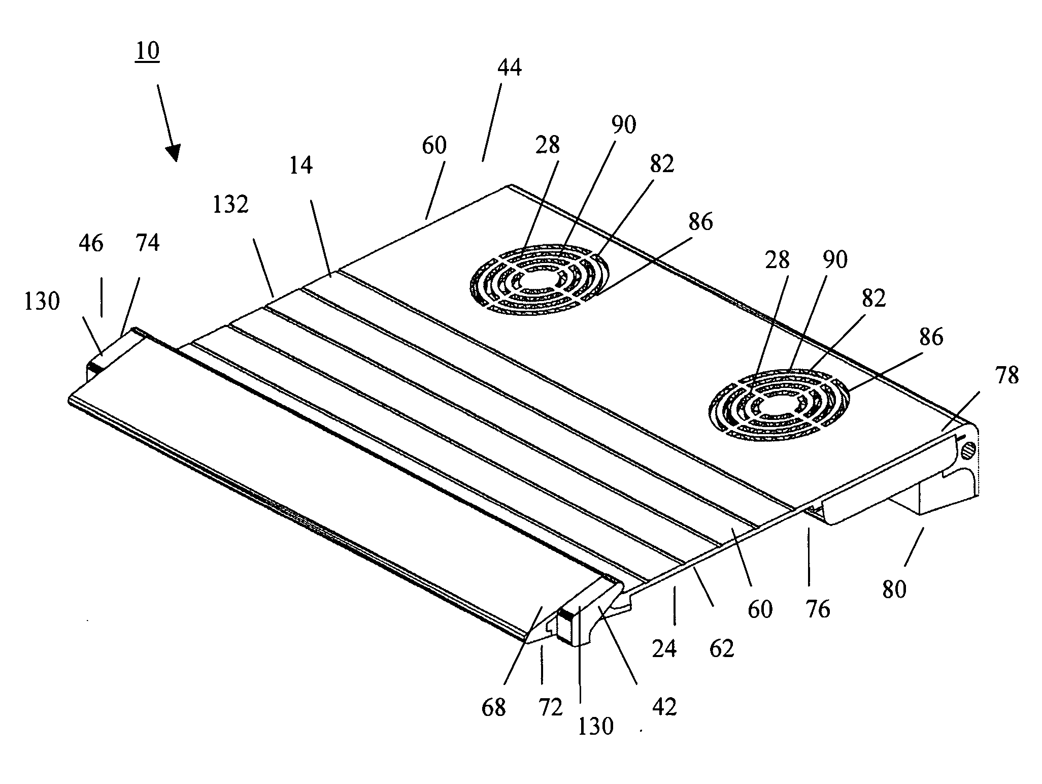
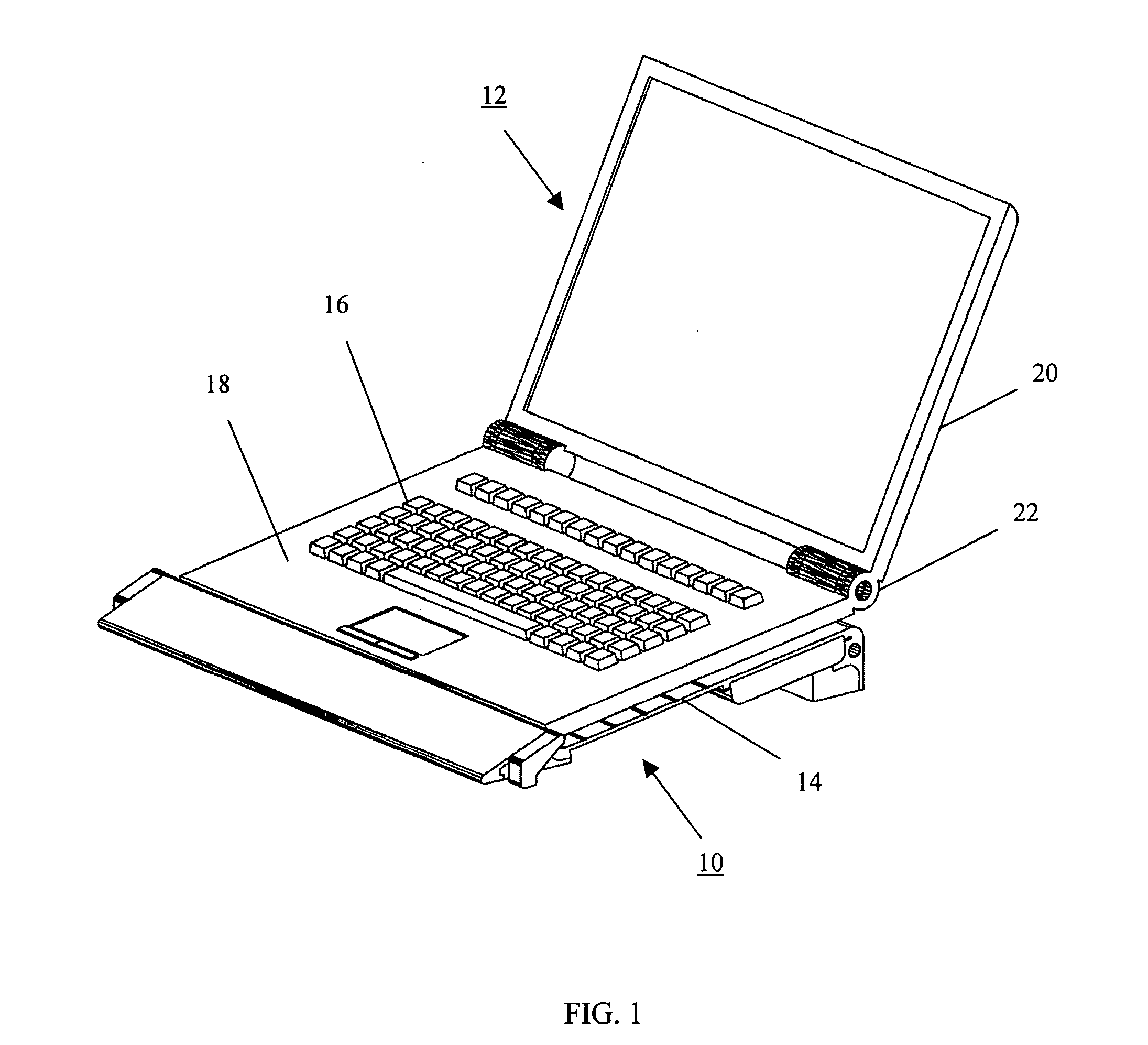
[0046]Reference is now made to FIG. 1 illustrating a moveable platform 10 for a laptop computer 12, which supports the laptop computer on an angled support base 14 of the moveable platform.

[0047]The laptop computer 12 has a keyboard 16 housed in a generally flat rectangular base structure 18. The display monitor 20 is connected by a hinge 22 to the base structure 18. The processing unit, hard drive, optical drives, USB ports and other electrical components of the laptop computer are in the base structure.

[0048]When the laptop computer is not in operation or when the laptop computer is being stored, the display monitor is usually folded flat over the base structure to provide a compact structure.

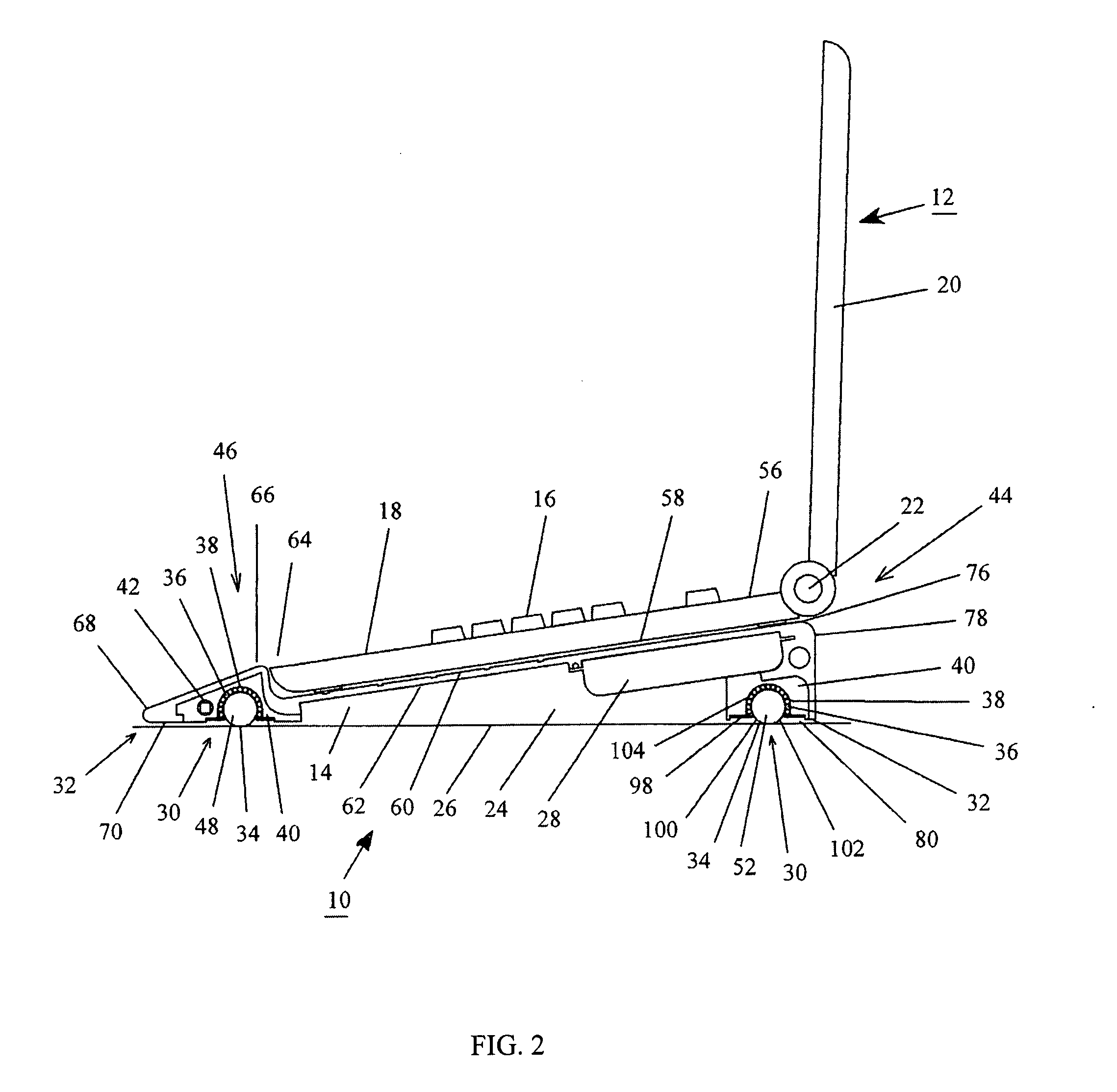
[0049]As best seen in FIG. 2, the moveable platform 10 has an angled support base 14, which tilts the keyboard 16 of the laptop base structure 18 while elevating the display monitor 20 of the laptop 12.

[0050]The angled support base 14 forms an airgap 24 between the moveable platform 10 and th...


PUM


Abstract

A moveable platform for a laptop computer has an angled support base to angle the laptop keyboard and elevate the laptop display monitor. The angled support base forms an airgap between the moveable platform and the desktop to dissipate the heat from the laptop computer. A separate cooling fan system integral with the support base can also dissipate the laptop computer heat. Spherical roller assemblies on the bottom of the platform move the laptop computer around the desktop. The spherical roller assemblies have a Teflon™ spherical ball surrounded by a plurality of Delrin™ spherical ball bearings in a Nylon™ semi-spherical cavity. These non-metallic materials provide smooth quiet operation with minimal frictional resistance and are non-abrasive to the desktop surface. A braking mechanism at the front of the moveable platform lifts the front spherical roller assemblies from contact with the desktop to lock the moveable platform and laptop computer into position on the desktop.

Description

BACKGROUND OF THE INVENTION[0001]This invention relates generally to a platform for a laptop computer and, more particularly, this invention is directed to a moveable platform for a laptop computer.[0002]Laptop computers, often referred to as notebook computers, are used extensively by people that seek computer availability while traveling and at a variety of locations.[0003]Laptops offer an alternative to bulkier, space consuming desktop computers, with the opportunity to readily take the laptop to lectures, business meetings, or the like.[0004]The reduction in the size and weight of today's laptop computers render them indispensable to travelers and business people.[0005]A laptop computer has become the computer of choice. Many people continue to use the laptop computer in an office or home environment over a desktop computer, from force of habit and the need for access to files on the laptop.[0006]As a result, users are often required to operate the laptop computer directly on an...

Claims


Application Information

Patent Timeline
Patent Type & Authority Applications(United States)
IPC IPC(8): A47G29/00H05K5/00
CPCA47B2023/049F16M13/00G06F1/1616G06F1/1632G06F1/1656G06F1/203F16M11/22F16M11/42
Inventor JACOBS, CARL V.HITT, DONALD W.
Owner JACOBS CARL V
Why Eureka
Try Eureka