Invisible target illuminators for 3D camera-based alignment systems

a technology of target illumination and camera-based alignment, which is applied in the field of target illumination, can solve the problems of operator eye strain and red light can be distracting for the operator, and achieve the effects of reducing eye strain, increasing power output, and increasing eye strain

Inactive Publication Date: 2005-03-24
SNAP ON INC
View PDF38 Cites 30 Cited by
  • Summary
  • Abstract
  • Description
  • Claims
  • Application Information

AI Technical Summary

Benefits of technology

[0012] One advantage of the present disclosure is to provide a 3-D camera based alignment system that reduces eye strain, and that provides for increased power output without an increase in eye strain.
[0013] Another advantage of the present disclosure is to provide a 3-D camera based aligner that is less distracting to the operator.
[0014] Another advantage of the present disclosure is to provide directional indicators that are readily visible to a wheel alignment technician. These directional indicators indicate a direction in which the vehicle should be moved or steered to assist in proper alignment.
[0015] Another advantage of the present disclosure is to provide wheel indicators that are easily visible to a wheel alignment technician. These wheel indicators indicate to the technician whether the alignment software has successfully acquired the target attached to a vehicle's wheels.

Problems solved by technology

Light sources in the visible red spectrum may cause operator eye strain.
Moreover, red light can be distracting to the operator.

Method used


Image

  • Invisible target illuminators for 3D camera-based alignment systems
  • Invisible target illuminators for 3D camera-based alignment systems
  • Invisible target illuminators for 3D camera-based alignment systems

Examples


Embodiment Construction

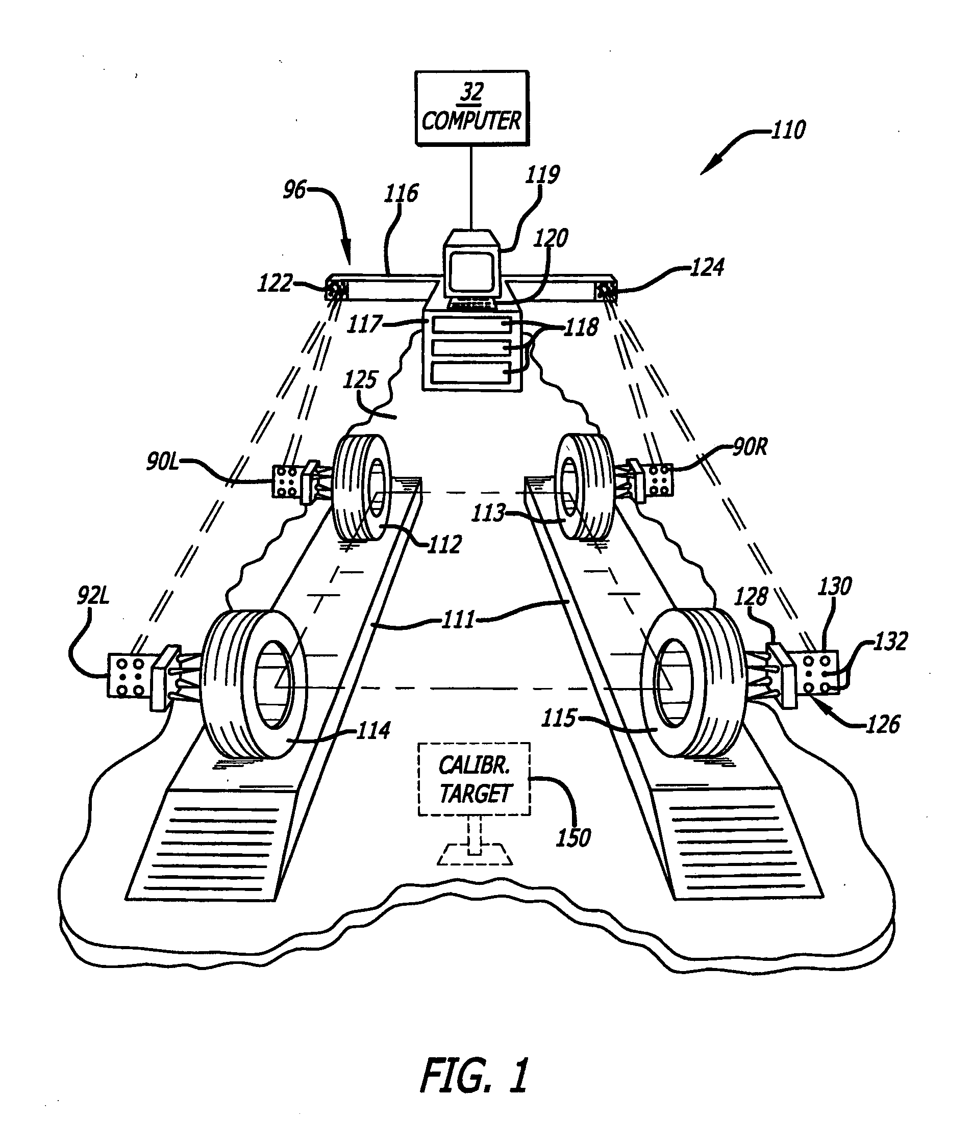
[0024] Wheel alignment systems may use a vision imaging system that employs image (or optical) sensing devices to determine the positions of various target devices. These types of wheel alignment systems are capable of obtaining positional information about a vehicle, such as ride height, toe curve, tilt angle, and the angular relationship of the vehicle's body relative to the vehicle's wheels. Three-dimensional camera based wheel aligners employ image sensing devices such as cameras to determine the positions of various target devices. Although such vision imaging systems are typically used for alignment purposes, these systems can also be used to obtain other positional and angular orientation information about a motor vehicle. Devices capable of obtaining this additional information are referred to herein as position determination systems.

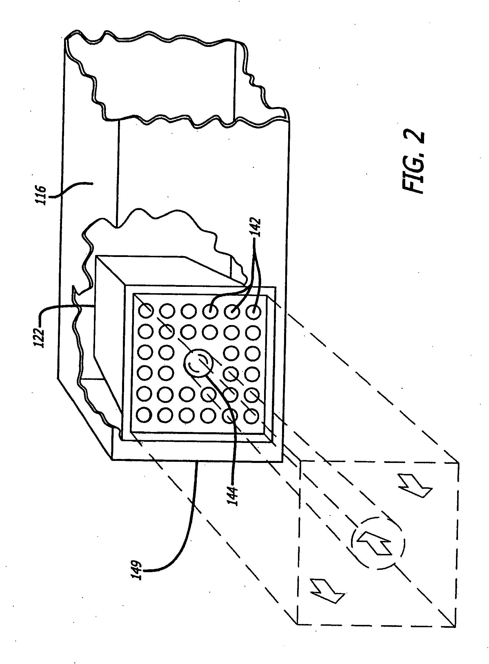
[0025] An example of a position determination system (including a wheel alignment system) on which the present disclosure may be implemented i...


PUM


Abstract

A three-dimensional camera based system for determining the position and/or alignment of objects such as motor vehicle wheels. The system includes a strobed infrared lighting subsystem, a visible indicator that the subsystem is working properly, and targets for attachment to the objects. The system also includes at least one camera for viewing the targets, and a data processor connected to the camera for processing data relating to images of the targets to determine position and/or alignment information, and a display that displays the position and/or alignment information. The system includes directional indicators for indicating that the vehicle should be repositioned by moving it backward, forward, or steered left or right. The system also includes wheel indicators tied in with software on the data processing device. These wheel indicators indicate the state of target acquisition by the data processing device based on the image from the camera.

Description

FIELD OF THE DISCLOSURE [0001] The present disclosure relates generally to motor vehicle alignment and, more particularly, to target illuminators outside the visible light spectrum that are suitable for three-dimensional camera based alignment systems. BACKGROUND OF THE DISCLOSURE [0002] Wheel alignment systems are capable of obtaining position or orientation information about a vehicle, such as ride height, toe curve, tilt angle and the angle of a vehicle's body relative to the vehicle's wheels. [0003] The wheels of a motor vehicle may be aligned using a vision imaging system, such as a computer-aided, three-dimensional (3D) machine vision that employs image sensing devices, such as cameras to determine the position of various target devices. Although such imaging systems are typically used for alignment purposes, these systems can also be used to obtain other positional and angular orientation information about a vehicle. Examples of such apparatuses and methods are described in U...

Claims


Application Information

Patent Timeline
Patent Type & Authority Applications(United States)
IPC IPC(8): G01B11/275H04N5/225
CPCG01B11/2755G01B2210/143H04N5/2259G01B2210/30H04N5/2256G01B2210/26H04N23/58H04N23/56
Inventor JACKSON, DAVID A.BRYAN, ERIC F.ROBB, MICHAEL J.
Owner SNAP ON INC
Why Eureka
Try Eureka