

Microchannel and Microfluid Chip
a microchannel and microfluid technology, applied in the field of microchannels and microfluid chips, can solve the problems of escaping from the groove, affecting the measurement effect, so as to achieve efficient capture, efficient capture, and quick and accurate measurement
- Summary
- Abstract
- Description
- Claims
- Application Information
AI Technical Summary
Benefits of technology
Problems solved by technology
Method used
Image

Examples
first embodiment
(1) Structure of Microchannel
[0042]The microchannel is formed on the inside of a microfluid chip, in the desired two-dimensional and / or three-dimensional shape so as to allow the passage of a sample (a liquid, gas, etc., and preferably a liquid).
[0043]There are no particular restrictions on the planar shape of the microchannel, which can be set as desired after taking into consideration the intended application, size, and so forth. The cross sectional shape of the microchannel (a cross section perpendicular to the direction of fluid flow) may be, for example, square, trapezoidal, or another polygonal shape, one of these shapes in which the corners have been rounded, or circular, elliptical, or dome shape, or a non-uniform shape with left and right asymmetry, or any other shape. The purpose of the microchannel is to allow the flow of a tiny amount of sample, preferably a liquid sample, and as long as that purpose is suitably fulfilled, there are no particular restrictions on its size...
embodiment 1
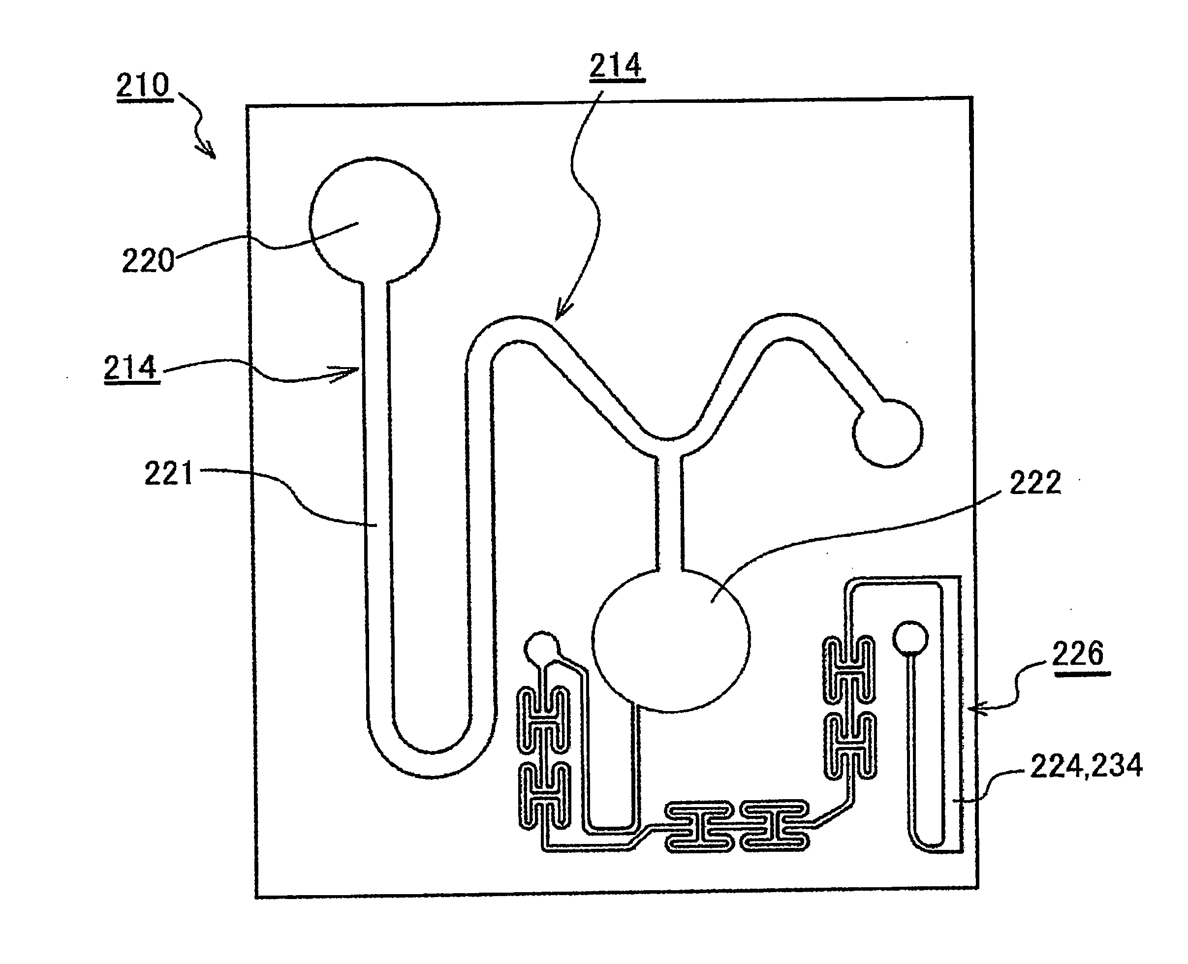
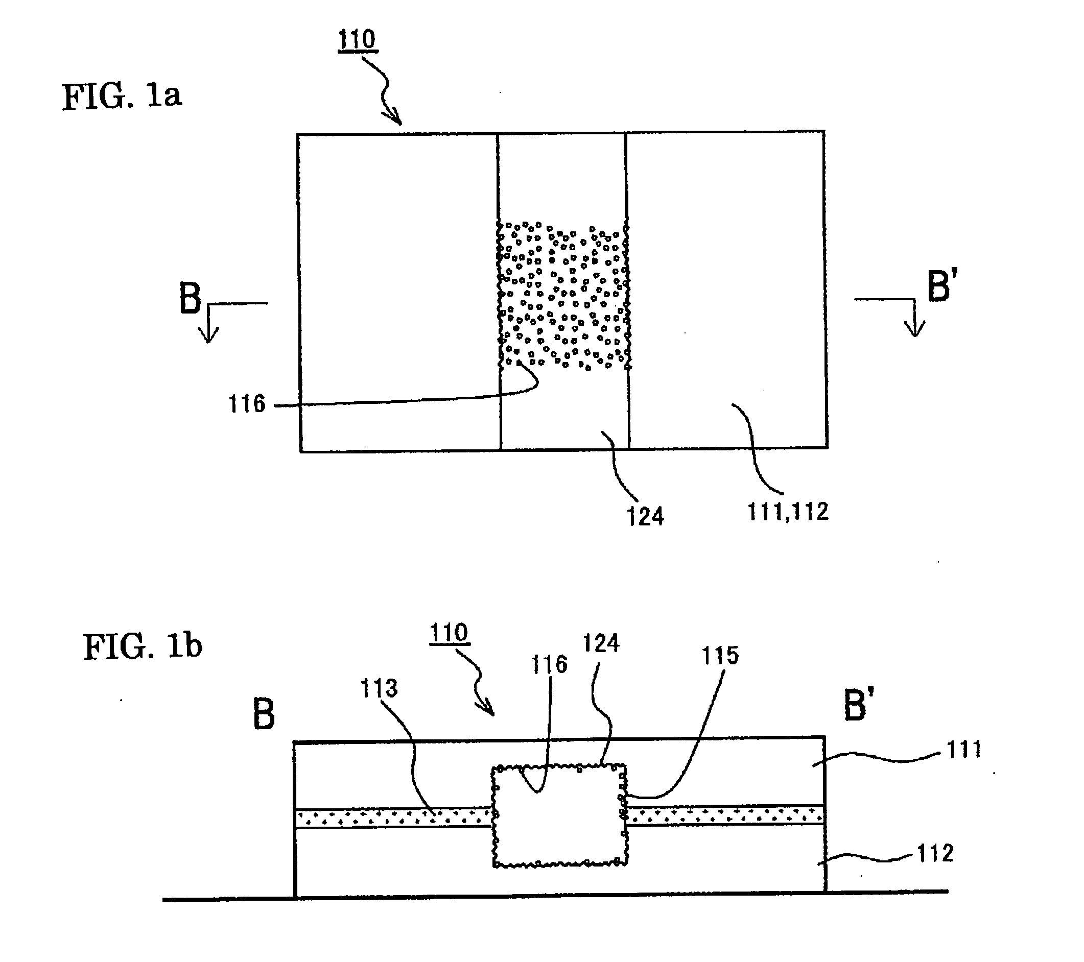
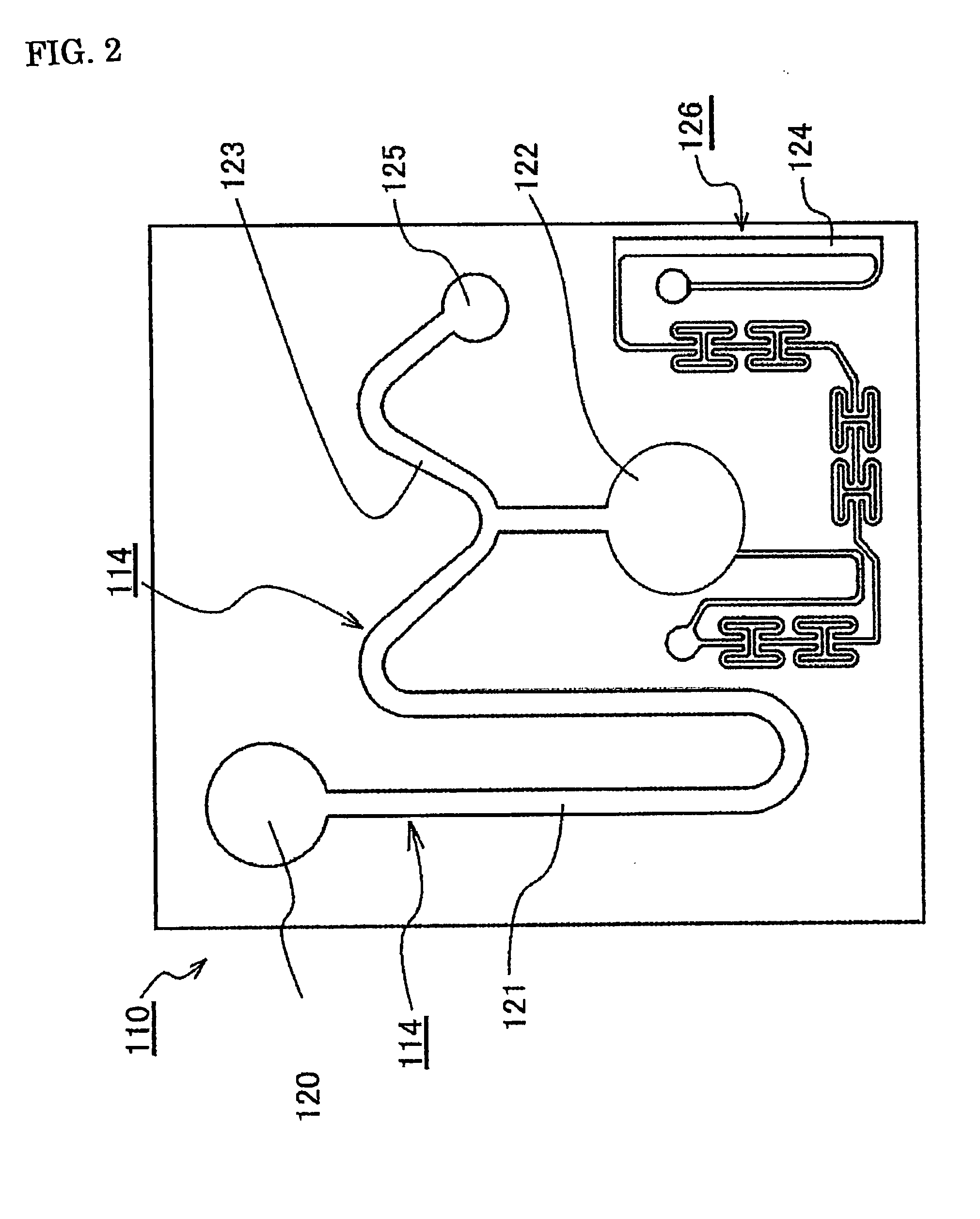
[0065]As shown in FIGS. 1a and 1b and FIG. 2, a microchannel and microfluid chip of the present invention are formed by substrates 111 and 112 composed of PET and having a thickness of 1 mm with patterns corresponding to microchannels 114 and 124 formed on the surface thereof. These substrates 111 and 112 can be formed by molding in a metal mold. When the substrates 111 and 112 having patterns of the microchannels 114 and 124 in this manner are for example, stuck together via an adhesive 113 with the patterns facing each other, a microfluid chip 110 on the inside of which the microchannels 114 and 124 are formed is obtained.
[0066]With this microfluid chip 110, for example, first the sample is introduced through a sample introduction port 120. The introduced sample is moved through a centrifugal separation unit 121 to a reservoir 122 by centrifugal force or the like obtained by rotating the microfluid chip 110. The sample goes from the reservoir 122 through the microchannel 114, and ...
embodiment 2
[0071]As shown in FIGS. 3a and 3b, the microchannel in this embodiment was set to a width of 300 μm, a depth of 100 μm, and a length of 10 mm so that when light was transmitted through the microchannel 114 at a location corresponding to the measurement unit of the microfluid chip shown in FIG. 2, the component concentrations in the sample could be detected from the transmissivity.
[0072]Fine depressions with a width and depth of about 0.5 μm were locally formed in a density of 9×10⁶ depressions per square millimeter on both side faces on the inside of the microchannel 114.
[0073]A sample and a reagent that had been stored at 4° C. were injected through the introduction port 120 into this microfluid chip, and the entire microfluid chip was heated to 40° C. to promote the reaction between reagent and sample.
[0074]The gas component corresponding to the amount of change in the saturation solubility in response to temperature change vaporized and produced bubbles here, but nearly all the b...
PUM
 Abstract
Description
Claims
Application Information